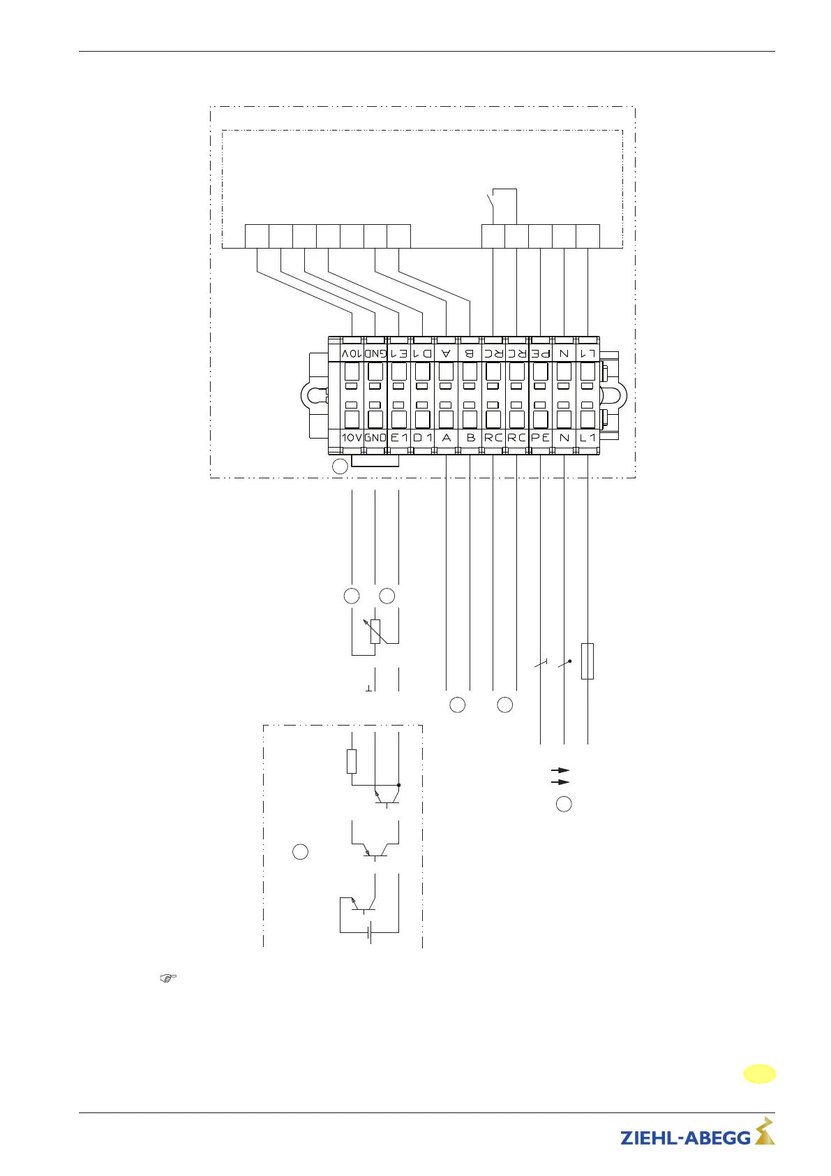
EasyManuals Logo

Siemens SIMOTICS M-1PH8 User Manual

Siemens SIMOTICS M-1PH8
198 pages
To Next Page IconTo Next Page
To Previous Page IconTo Previous Page
Page #189 background imageLoading...
Page #189 background image
9.2 Connection diagram
A1
10V GND E1 D1
11 14
DC Out
Analog In
Digital In
GR25V-6IK.BD.1R / GR31M-6ID.BD.2R
EMUN19K1
29.04.2015
K1
max. AC 250 V 2 A
Signal
0...10 V
+
Signal PWM
f = 1...10 kHz
7
6 5
2
10 kΩ
10 kΩ
10 V
GND
E1
E1
GND
15...28 V
+
-
L1NPE
Netzspannung
Leistungsschild
Line voltage Rating-plate
1
A
(D+)
B
(D-)
MODBUS
(RS-485)
3
10 V
E1
4
1 Line voltage
rating plate
2 Relay output for fault indication (contact rating max. AC 250 V 2 A)
3 MODBUS (RS-485) interface
4 Factory-installed bridge between 10 V and E1 for 100 % speed
5 Input for speed setting by 0...10 V signal / potentiometer (R
i
> 100 k)
6 Voltage supply 10 V DC (I
max
50 mA)
7 Speed setting by PWM signal (f = 1...10 kHz)
Assembly instructions ECblue Enclosure
L-BAL-F065-GB 1617 Index 004 Part.-No. 00702801-GB
25/28
189

Table of Contents

Other manuals for Siemens SIMOTICS M-1PH8

Questions and Answers:

Question and Answer IconNeed help?

Do you have a question about the Siemens SIMOTICS M-1PH8 and is the answer not in the manual?

Siemens SIMOTICS M-1PH8 Specifications

General IconGeneral
BrandSiemens
ModelSIMOTICS M-1PH8
CategoryEngine
LanguageEnglish

Related product manuals