Alarm, error, and system messages
9.2 Combinations of LED displays
SIMOTION C
Operating Instructions, 02/2012
169
9.2 Combinations of LED displays
Combination of LED displays
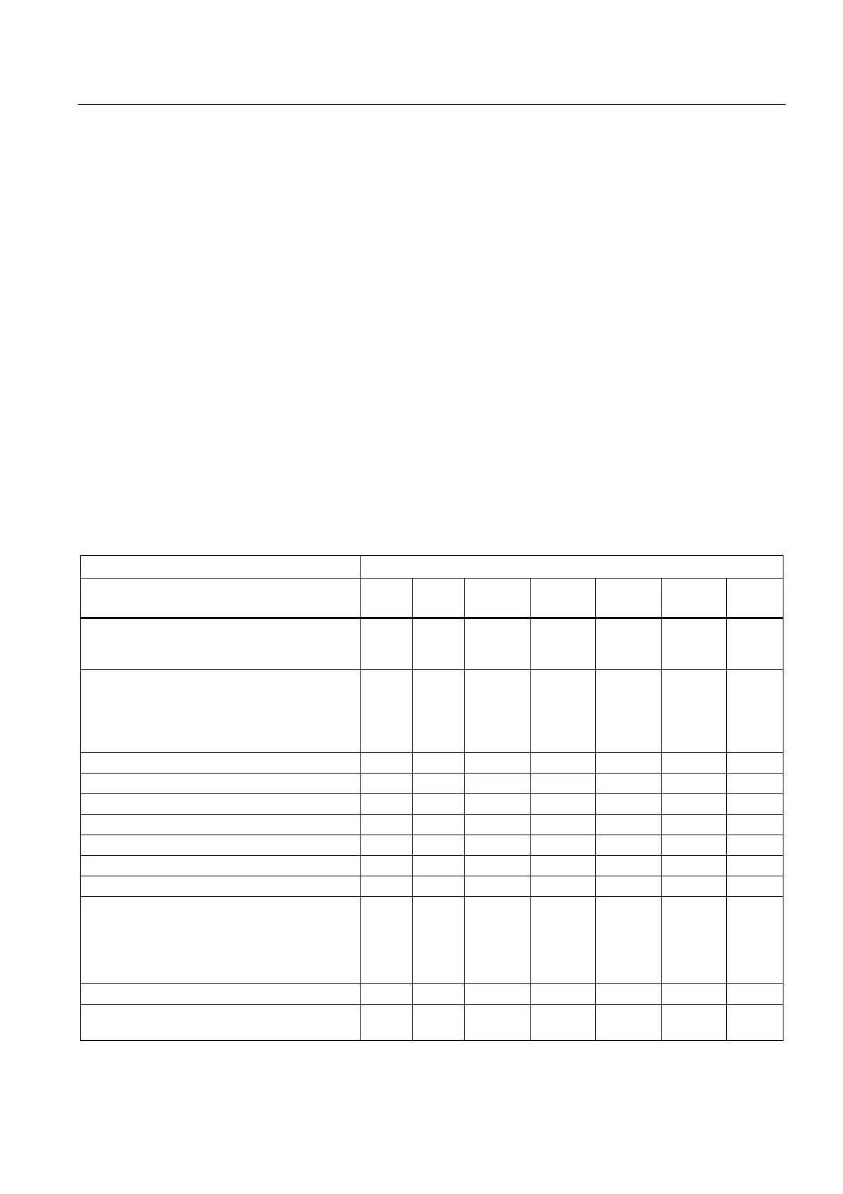
The following table provides an overview of all permissible and/or required LED display
combinations.
The meaning of the symbols used in the table is as follows:
1 LED on
0 LED off
0,5/1 LED flashing (0.5 Hz)
2/1 LED flashing (2 Hz)
☆ LED flickers
→ Running light
x LED may light up
Table 9- 3 Summary of LED displays
Meaning LED displays
SF
(red)
5 VDC
(green)
RUN
(green)
STOPU
(yellow)
STOP
(yellow)
BUS1F
(red)
BUS2F
(red)
Ramp-up (C230-2) 1
0
0
1
1
1
1
0
0
1
☆
0
1
0
2/1
1
0
0
1
0
0
Ramp-up (C240 / C240 PN) 1
0
0
0
0
1
1
1
1
1
1
☆
0
0
0
1
0
☆
→
0
1
0
0
→
2/1
1
0
0
0
0
1
0
0
0
0
STOPU → RUN x 1 2/1 1 0 x x
RUN x 1 1 0 0 x x
RUN → STOPU x 1 1 2/1 0 x x
STOPU x 1 0 1 0 x x
STOPU → STOP x 1 0 1 2/1 x x
STOP x 1 0 0 1 x x
STOP → STOPU x 1 0 2/1 1 x x
Defective operating mode
To correct or avoid errors:
Switch SIMOTION C Off/On
Check diagnostic buffer
0 1 1 ☆ ☆ ☆ ☆
Power supply is ready for operation x 1 x x x x x
Write to micro memory card
(copy RAM to ROM)
x 1 0 0 ☆ x x

 Loading...


