Interfaces
3.6 Onboard measuring system interface (C230-2, C240)
SIMOTION C
62 Operating Instructions, 02/2012
Note
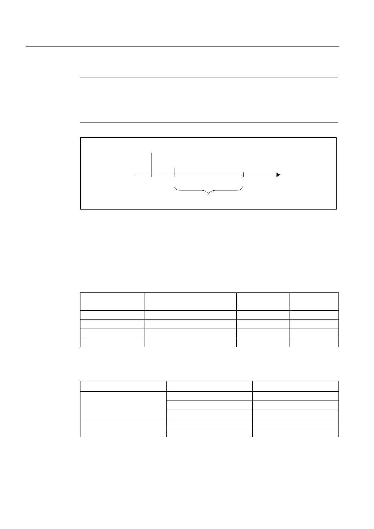
With certain selected set values for the position control cycle clock, the measured value
sampling in the C240 takes place at time Ti before the position control cycle clock time, see
"Actual value latch time" table, in chapter Technical data (Page 171). This behavior is similar
to that of PROFIBUS DP encoders
.
$FWXDOYDOXHODWFKWLPH
3RVLWLRQFRQWUROF\FOHFORFNWLPH
3RVLWLRQFRQWUROF\FOH
7
L
7
W
Figure 3-12 Position control cycle
Connecting cable to the encoder
The maximum cable length depends on the specification for the encoder supply and the
baud rate. For problem-free operation, you must not exceed the following values when using
SIEMENS preassembled connecting cables (see
Catalogs PM 21/NC 60/ST 70
):
Table 3- 14 Maximum cable lengths, depending on the encoder power supply
Supply voltage Encoder supply voltage range Current
consumption
Max. cable length
5 VDC 4.75 V to 5.25 V < 300 mA 25 m
5 VDC 4.75 V to 5.25 V < 210 mA 35 m
24 VDC 20.4 V to 28.8 V < 300 mA 100 m
24 VDC 10 V to 30 V < 300 mA 250 m
Table 3- 15 Maximum cable lengths, depending on the baud rate
Encoder type Frequency° Max. cable length
1 MHz 10 m
500 kHz 35 m
Incremental encoder
300 kHz 100 m
1.5 Mbits/s 10 m Absolute encoder (SSI)
187.5 Kbyte/s 250 m

 Loading...


