10.99 Connecting-up
Siemens AG 6SE7087-6KP50
SIMOVERT MASTERDRIVES Operating Instructions 7-7
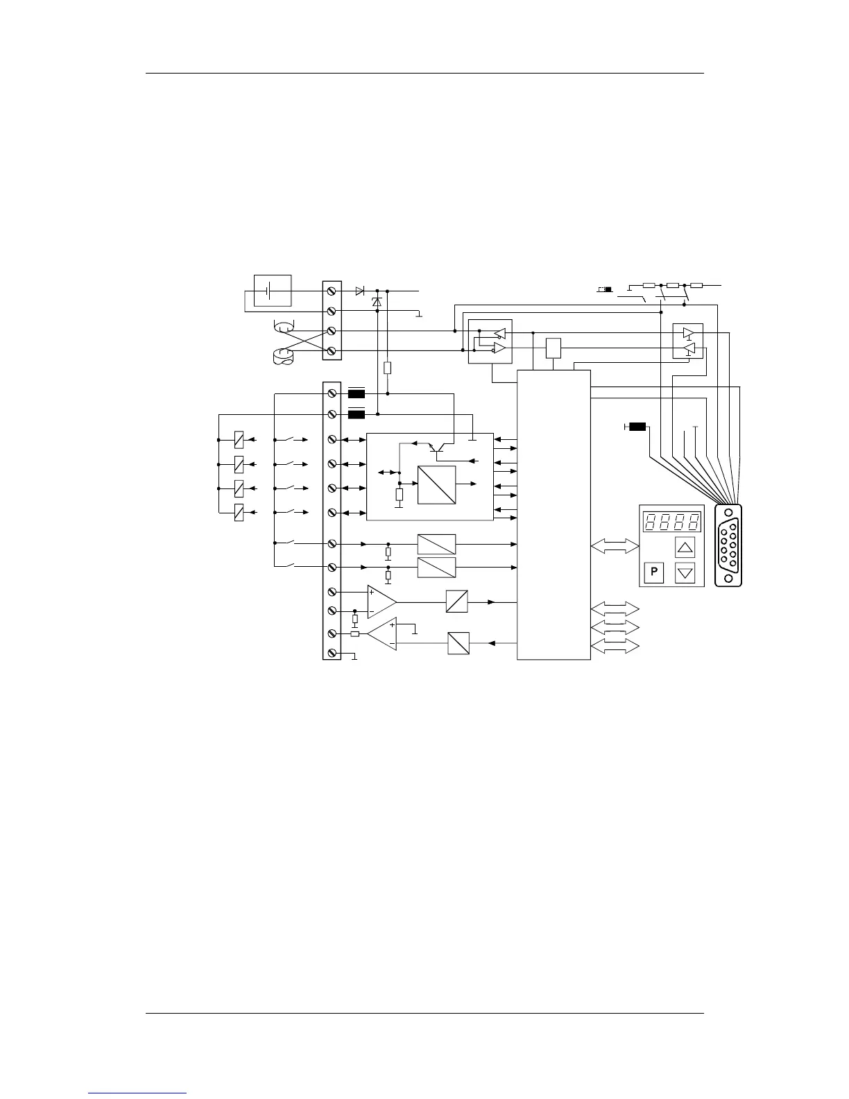
7.2 Control connections
The basic version of the unit is provided with the following control
connections:
♦
external 24V supply, USS bus connection (RS485)
♦
serial interface for PC or OP1S
♦
control terminal strip.
Two-way
digital inputs
and outputs
X101
5V
24V
In
Out
Out
In
Out/In
In
Out
In
Out
In
Out
In
Out
In
4 two-waydigital inputs/outputs
Outputs
Analog input
P24V
M24
Aux. powr
supply
Analog output
5V
24V
In
Inputs
5V
24V
2
1
3
4
5
6
7
8
9
10
11
12
Micro-
controller
D
A
D
A
Serial USS
interface (RS485)
RxD
RS485N
EN_RS485
+5V
RS485P
33
34
35
36
+
24V
-
P24V
M24
TxD
P5V
RS485P
RS232 Id
RS485P
BOOT
RS232 TxD
RS485N
EN_RS232
≥
1
External 24 V
supply
S1
X103
X100
Switch for
USS bus connection
Digital inputs
OFFON
123456789
BOOT
RS232 Id
RS232 RxD
RS485N
Slot A
Slot B
Slot C
Controller
Fig. 7-4 Overview of the standard connections
Standard
connections