Parameterization 10.99
6SE7087-6KP50 Siemens AG
8-2 Operating Instructions SIMOVERT MASTERDRIVES
8.1 Parameter input via the PMU
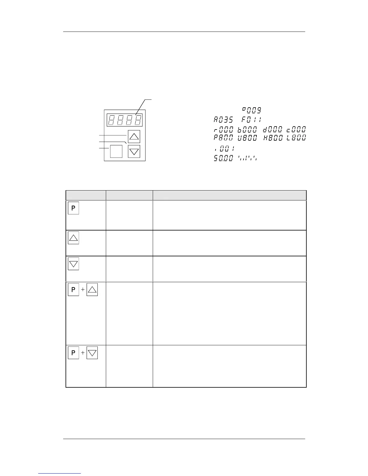
The PMU parameterizing unit enables parameterization, operator
control and visualization of the converters and inverters directly on the
unit itself. It is an integral part of the basic units. It has a four-digit
seven-segment display and several keys.
P
Lower key
Toggle key
Raise key
Seven segment display for:
drive statuses
Alarms and faults
Parameter numbers
Parameter indices
Parameter values
Fig. 8-1 PMU parameterizing unit
Key Significance Function
Toggle key • For switching between parameter number, parameter index
and parameter value in the sequence indicated (command
becomes effective when the key is released).
• If fault display is active: Acknowledge the fault
Raise key For increasing the displayed value:
• Short press = single-step increase
• Long press = rapid increase
Lower key For lowering the displayed value:
• Short press = single-step decrease
• Long press = rapid decrease
Hold toggle key
and press raise
key
• If parameter number level is active: For jumping back and forth
between the last selected parameter number and the
operating display (r000)
• If fault display is active: For switching over to parameter
number level
• If parameter value level is active: For shifting the displayed
value one digit to the right if parameter value cannot be
displayed with 4 figures (left-hand figure flashes if there are
any further invisible figures to the left)
Hold toggle key
and press lower
key
• If parameter number level is active: For jumping directly to the
operating display (r000)
• If parameter value level is active: For shifting the displayed
value one digit to the left if parameter value cannot be
displayed with 4 figures (right-hand figure flashes if there are
any further invisible figures to the right)
Table 8-1 Operator control elements on the PMU