SINAMICS G130
Engineering Information
SINAMICS Engineering Manual – November 2015
Ó Siemens AG
286/528
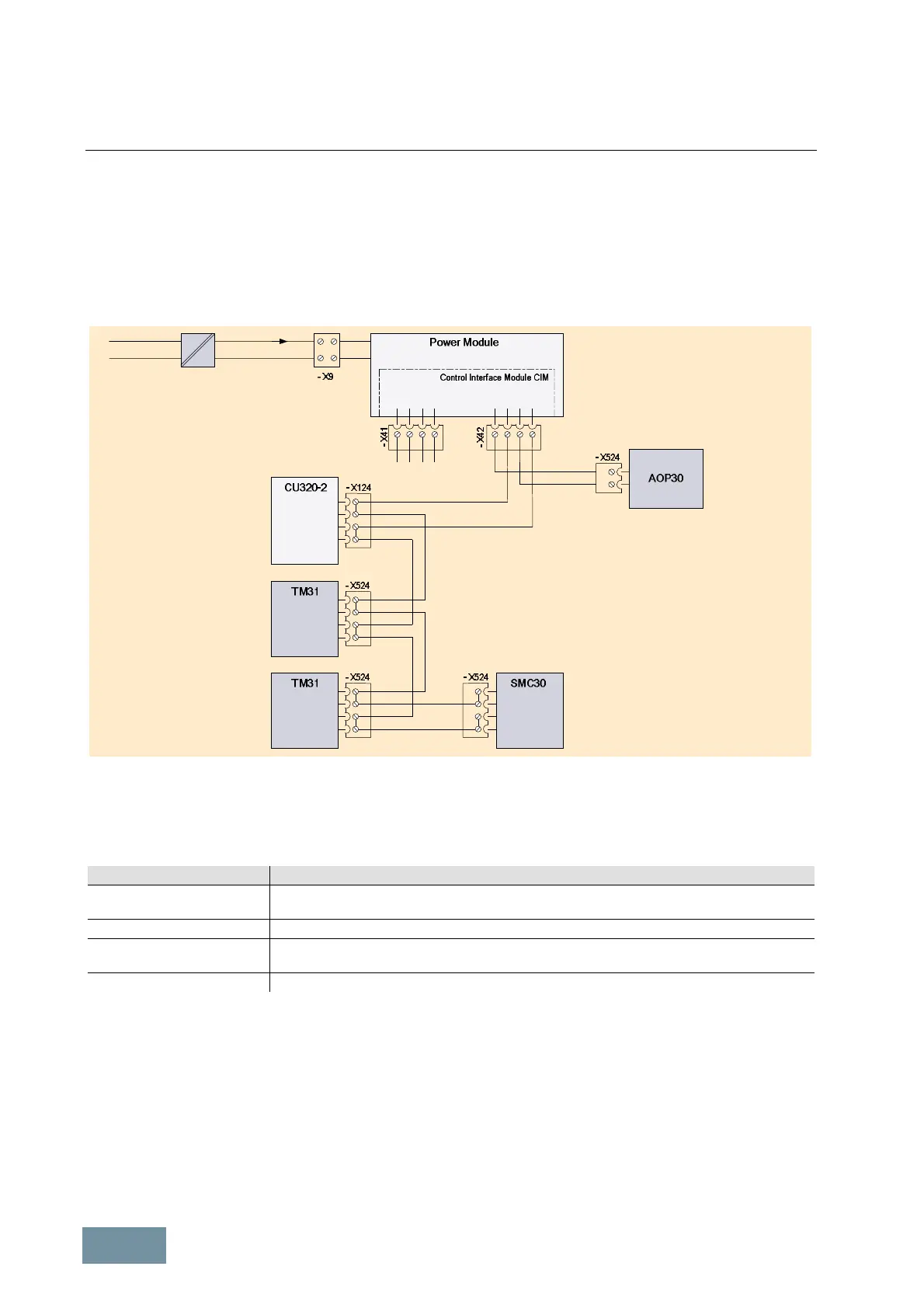
4.4 Incorporating different loads into the 24 V supply
A SINAMICS G130 Chassis unit comprises the Power Module and a CU320-2 Control Unit which requires a 24 V
power supply. In addition to the Control Unit, it may also be necessary to provide a 24 V supply to an AOP30
Operator Panel and/or one or two TM31 Terminal Modules, which are installed to expand the number of digital and
analog inputs and outputs. If the converter is feeding a motor with TTL/HTL incremental encoder, the SMC30 Sensor
Module must also be provided with a 24 V supply.
The diagram below shows how the different loads are incorporated into the 24 V supply system of the Power Module.
External 24V supply
1
2
P24
M
1
2
3
4
+ Temp
- Temp
EP + 24 V
EP M1
4
3
2
1
P24L
P24L
M
M
+
+
+
M
M
M
+
M
+
M
I DC ext 24 V DCe.g. 230 V AC
=
~
Incorporating different loads into the 24 V supply of a Power Module SINAMICS G130
The internal 24 V auxiliary power supply of the Power Module (voltage range 20.4 V to 28.8 V) is supplied from the
DC link of the power unit and provides (without connection of an external 24 V supply to terminal X9) a maximum
total output current of 2.5 A at the terminals of connector X42.
The power requirement of the components / modules which can be connected to X42 is specified in the table below.
Component / Module Power requirement
Control Unit CU320-2 1000 mA ignoring the assignment of the slot and the digital outputs. (Each digital output has an
electrical load rating of maximum 500 mA, depending on the connected load).
Operator Panel AOP30 100 mA without backlighting or 200 mA with backlighting.
Terminal Module TM31 200 mA ignoring digital outputs. (Each digital output has an electrical load rating of maximum
100 mA, depending on the connected load).
Sensor Module SMC30 200 mA ignoring the power requirement of the connected sensor.
Power requirement of the components / modules which can be connected to the 24 V auxiliary supply of the Power Module
If the power requirement of the loads (including the loads of digital outputs) connected to the terminals of connector
X42 exceeds the permissible value of 2.5 A, an external 24 V supply (e.g. SITOP Power), which is capable of
providing the current I
DC ext
to all the connected loads, must be connected to terminal X9. This might be necessary, for
example, if in addition to the CU320-2 Control Unit and the AOP30 Operator Panel, two TM31 Terminal Modules with
large loads at their digital outputs as well as an SMC30 Sensor Module for evaluating an incremental encoder are
also connected.
An external 24 V supply will also be required if the internal auxiliary power supply needs to remain active even when
the power unit is disconnected from the mains so that auxiliary power can no longer be provided by the DC link. This
might be the case, for example, if a main switch or main contactor is used and the communication link to the
converter must remain in operation even when the main switch or contactor is open.

 Loading...


