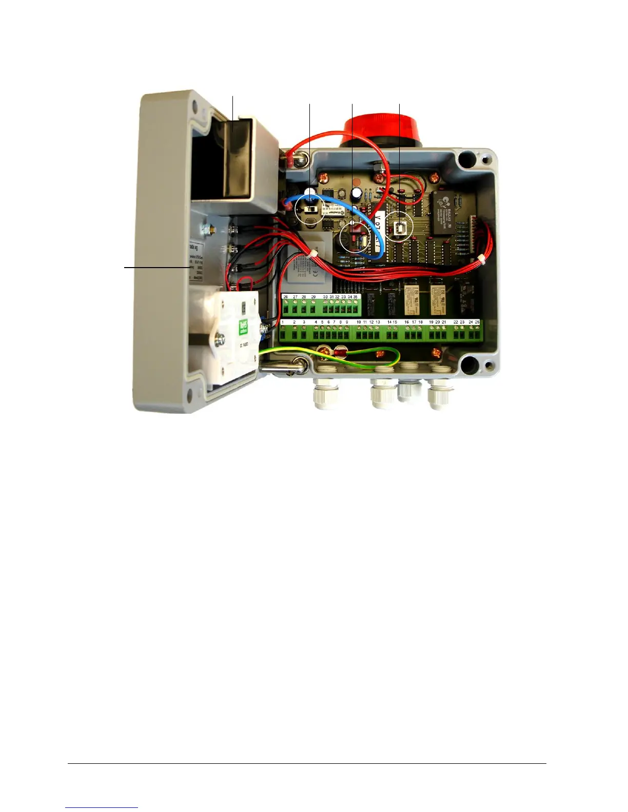
Interface connections
A For storage and transport, the red plug-in bridge (BR1) is fitted to just one pin. This
protect the battery from being unnecessary discharged. After commissioning, the red
plug-in bridges (BR1) must be fitted to both pins so that the battery will go into
operation.
B The power supply to the communication interface is switched on and off with the slider
switch.
Switch right = switched on
Switch left = switched off
C USB plug for the read-out of the system data.
D Battery for bridging over losses of the mains supply for up to 12 hours. (Refer to the
Maintenance and Repair Instructions for the replacement of the battery)
E Rating plate with all the information required by the regulations
The terminal configuration can be seen from connection diagram on the following page.