Operating and Programming — Milling Page 98 808D
ISO
Mode
s
Basic Theory
All the ISO codes described in this unit
can be implemented in the ISO mode of
the 808D system!
After pressing
“OK”, the sys-
tem restarts auto-
matically.
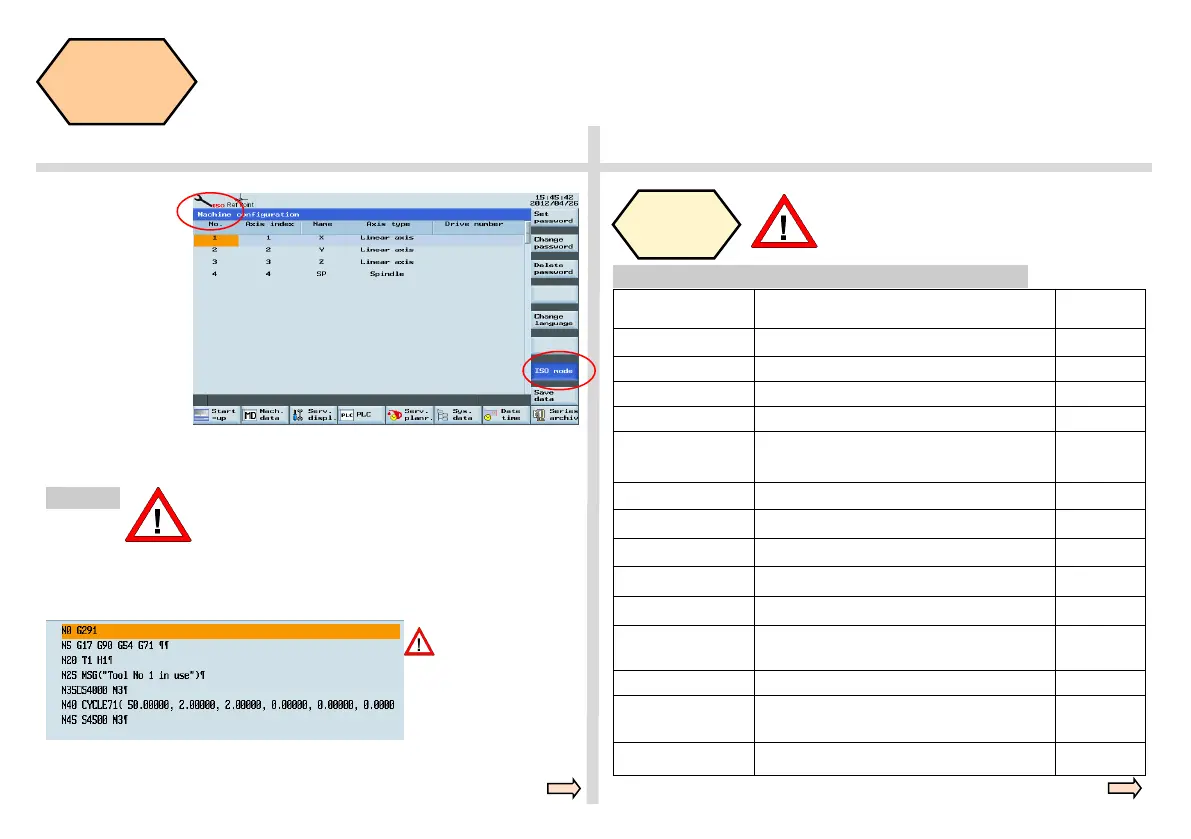
After restarting,
press “Shift” +
“System - Alarm”
again and if the
symbol in the red
circle appears,
ISO mode is al-
ready activated.
A red ISO appears at the top of the screen and the ISO mode button on
the right is highlighted in blue.
Method 2
When using method 2 to activate the ISO mode,
it will exit ISO mode and return to the default
DIN mode via “Reset” button or after finishing
the machining program.
G291/G290 com-
mands must be set
separately in a line!
Insert G291 in the first line of the ISO part program to be executed and
insert G290 in front of M30.
If ISO is displayed at the top of the screen, it is
activated.
ISO
code
explanation
ISO code Description Compare
with DIN
G00
Orientation (rapid traverse)
As DIN
G1 Linear difference As DIN
G17/G18/G19 XY plane / ZX plane / YZ plane As DIN
G20/G21 Input in inch/mm G70/G71
G41/G42/G40 Left tool tip radius compensation / right tool tip
radius compensation / cancel tool radius
compensation
As DIN
G54 ~ G59 Select workpiece coordinate system As DIN
G80 Cancel fixed cycle
G90/G91 Absolute/incremental programming
G94/G95 Feedrate F in mm/min / mm/r As DIN
S Spindle speed As DIN
,R Reverse circle (note the form there must be
”,” before R parameter)
RND
M3/M4/M5 Spindle right / spindle left / spindle stop As DIN
M98 P _L_
Subprogram call (P+ subprogram name/ L+
times)
Program
name + L
M99
End of Subroutine M17
Brief description of typical, frequently used ISO codes
 Loading...


