Connectable components
9.1 NX10/15
NCU 7x0.2
Manual, 02/2011, 6FC5397-0AP20-0BA0
91
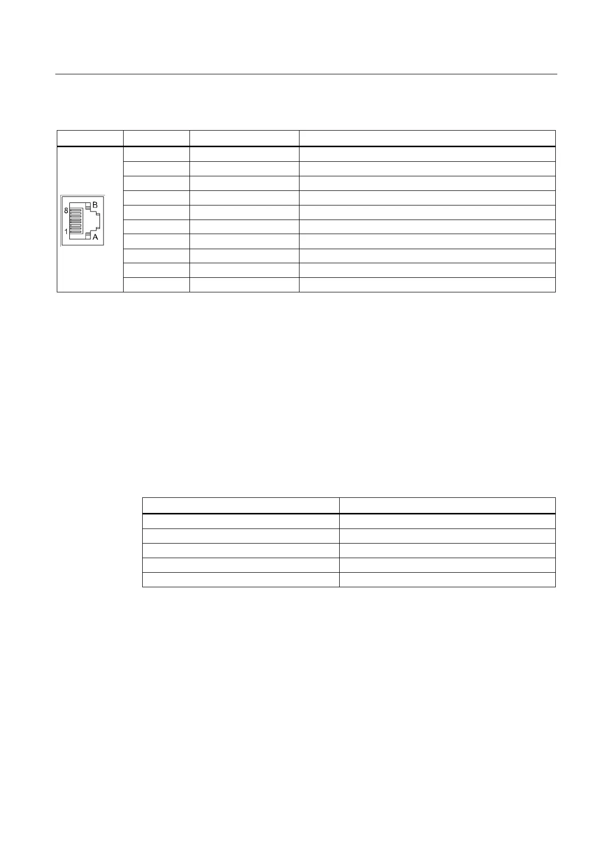
Table 9- 6 Pin assignment for X100 – X103
Pin Signal name Technical specifications
1 TXP Transmit data +
2 TXN Transmit data -
3 RXP Receive data +
4 - Reserved, do not use
5 - Reserved, do not use
6 RXN Receive data -
7 - Reserved, do not use
8 - Reserved, do not use
A + (24 V) Power supply
B G (0 V) Electronics ground
DRIVE-CLiQ topology
NX10/15 components can be connected to the control unit via DRIVE-CLiQ. The following
rules apply to wiring of the NX10/15:
● Only one star topology is permitted between the NX10/15 and the control unit. This
means that only one NX10/15 can be operated per DRIVE-CLiQ port on a control unit.
● DRIVE-CLiQ ports not assigned to NX10/15 can be wired to other DRIVE-CLiQ
components.
● Once an NX10/15 has been connected and configured, you cannot simply insert it into a
different DRIVE-CLiQ port, as the addresses of the integrated drives are set permanently
from the point of view of the PLC. The following table illustrates this relation:
Table 9- 7 NX10/15 PROFIBUS addresses
DRIVE-CLiQ port on the NCU Drive PROFIBUS addresses
X105 15
X104 14
X103 13
X102 12
X101 11
 Loading...


