Connectable components
9.1 NX10/15
NCU 7x0.2
92 Manual, 02/2011, 6FC5397-0AP20-0BA0
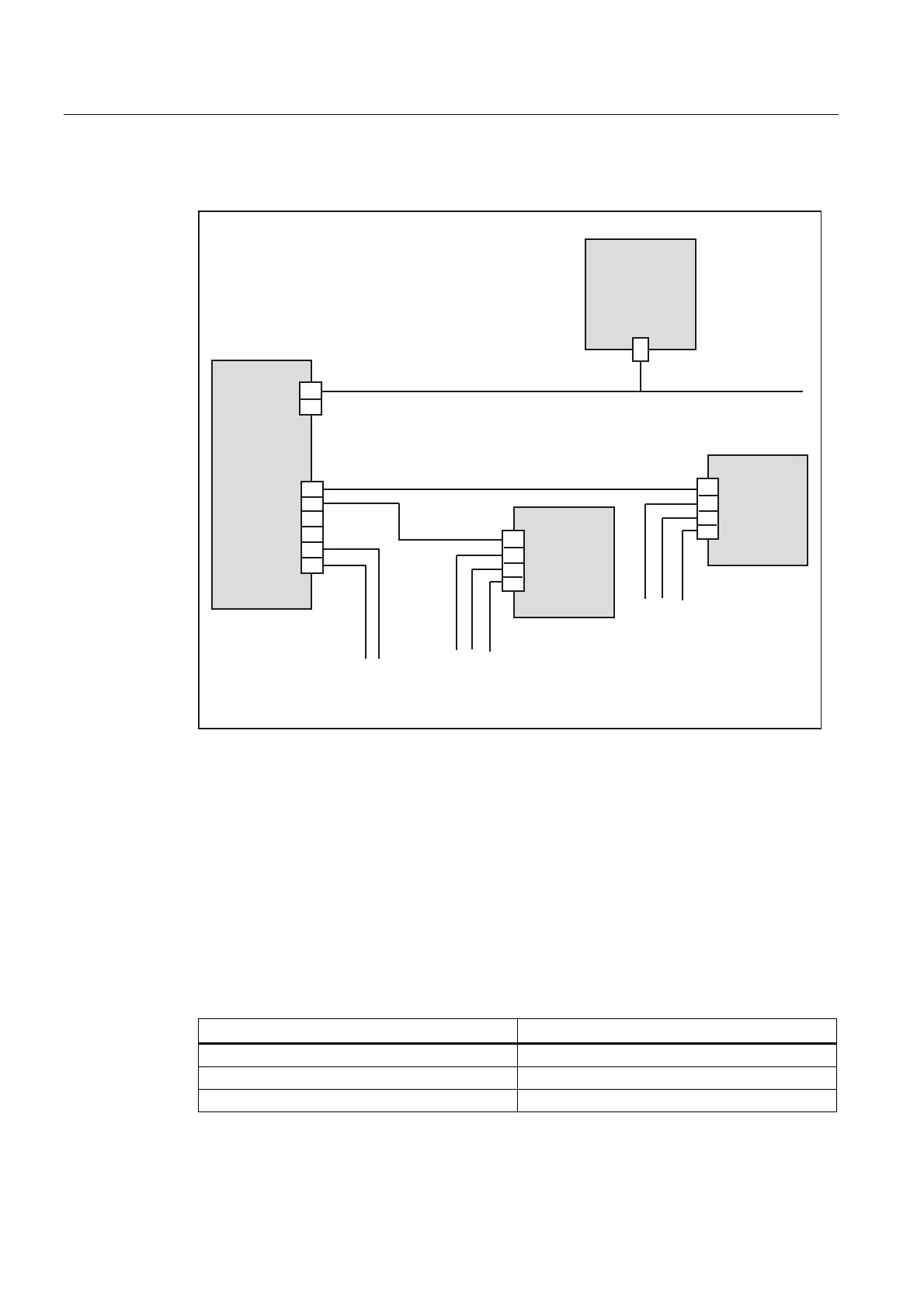
The following figure shows a sample topology:
([WHUQDO352),%86'3'3
6XEWRSRORJ\
1;
6XEWRSRORJ\
1;
'5,9(&/L4
FRPSRQHQWVRQWKH
1&8
'3DGGUHVV
(7
1&8
1;
1;
;
;
;
;
;
;
;
;
'3$GUHVVH
Figure 9-4 NX10/15 topology
X122 digital inputs/outputs
When commissioning the drive wizard, the digital inputs/outputs are correspondingly
preassigned functions.
For more information about terminal assignment, see:
● The "Communication in the system" section of the "Machine Configuration Guidelines"
System Manual
● The "IBN CNC: NCK, PLC, Drive" Commissioning Manual ("Tips" section)
Table 9- 8 Interface characteristics of X122
Characteristics Version
Connector type Screw-type terminals
Connection option Up to 0.5 mm
2
Current carrying capacity 4 A max.
 Loading...


