[dwocpka4-080213-01.tif, 2, en_US]
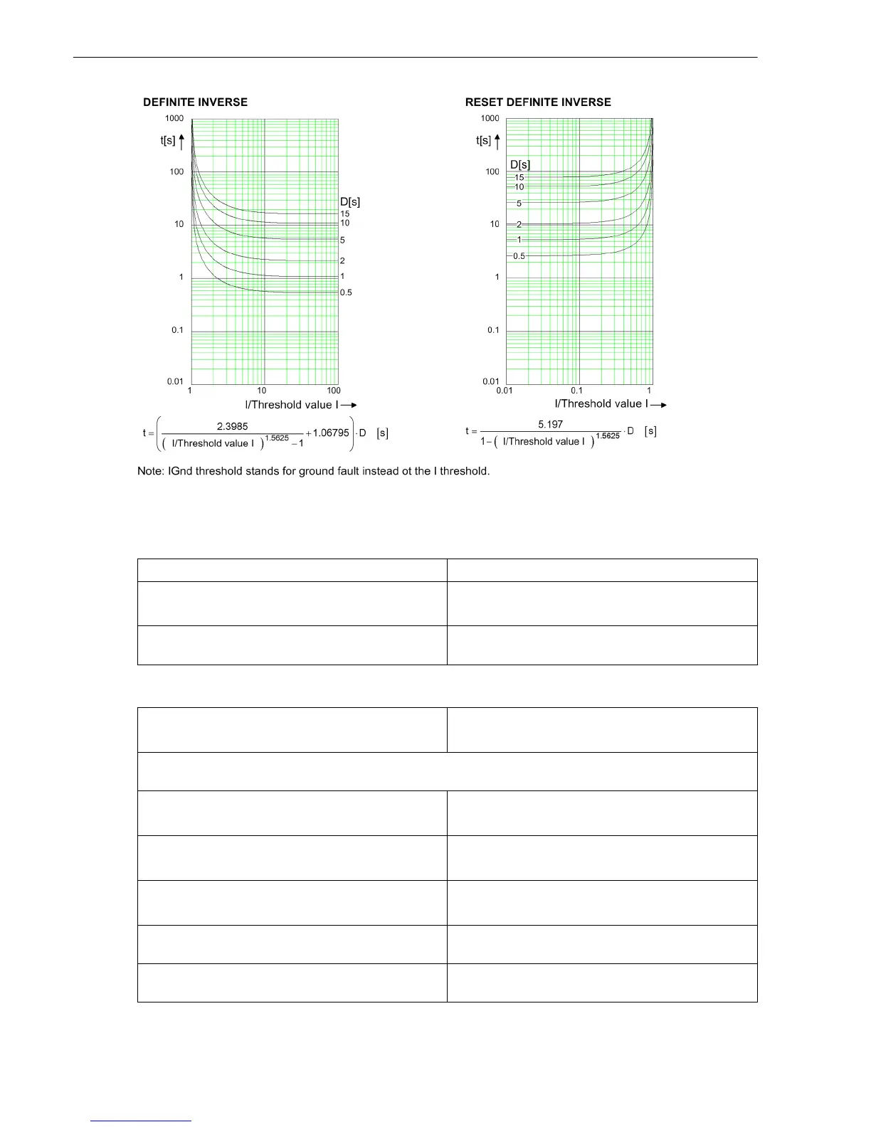
Figure 11-6
Operate Curves and Dropout-Time Characteristic Curves According to ANSI/IEEE
Frequency Operating Range
0.9 ≤ f/f
rated
≤ 1.1 According to specified tolerances
10 Hz ≤ f < 0.9 f
rated
1.1 f
rated
< f ≤ 80 Hz
Slightly expanded tolerances
f < 10 Hz
f > 80 Hz
Active
Tolerances
Currents, method of measurement = fundamental
component
1 % of the setting value or 5 mA (I
rated
= 1 A)
or 25 mA (I
rated
= 5 A), (f
rated
± 10 %)
Currents, method of measurement = RMS value
(33% harmonics, in relation to fundamental component)
Up to 30th harmonic 1 % of the setting value or 5 mA (I
rated
= 1 A)
or 25 mA (I
rated
= 5 A), (f
rated
± 10 %)
Up to 50th harmonic, f
rated
= 50 Hz 3 % of the setting value or 20 mA (I
rated
= 1 A)
or 100 mA (I
rated
= 5 A), (f
rated
± 10 %)
Up to 50th harmonic, f
rated
= 60 Hz 4 % of the setting value or 20 mA (I
rated
= 1 A)
or 100 mA (I
rated
= 5 A), (f
rated
± 10 %)
Operate time for 2 ≤ I/I threshold value ≤ 20 5 % of the reference (calculated) value
+2 % current tolerance or 30 ms
Dropout time for I/I threshold value ≤ 0.90 5 % of the reference (calculated) value
+2 % current tolerance or 30 ms
Technical Data
11.16 Stage with Inverse-Time Characteristic Curve
586 SIPROTEC 5, Low-Impedance Busbar Protection 7SS85, Manual
C53000-G5040-C019-6, Edition 06.2016

 Loading...