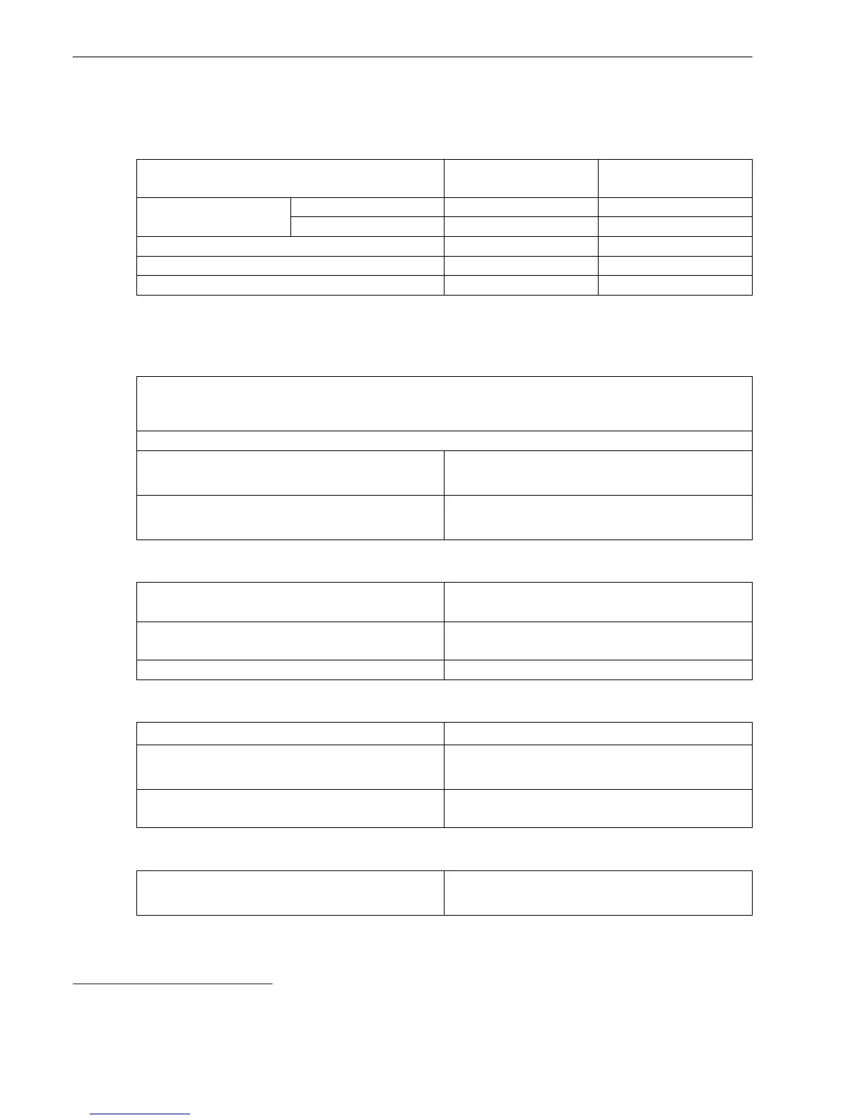
Stage with Definite-Time Characteristic Curve
Setting Values
Method of measurement Fundamental component
RMS value
–
Threshold value
20
1 A @ 100 Irated 0.030 A to 35.000 A Increments of 0.001 A
5 A @ 100 Irated 0.15 A to 175.00 A Increments of 0.01 A
Dropout ratio 0.90 to 0.99 Increments of 0.01
Time delay 0.00 s to 60.00 s Increments of 0.01 s
Dropout delay 0.00 s to 60.00 s Increments of 0.01 s
Dropout
The greater dropout differential (= | pickup value – dropout value |) of the following 2 criteria
applies:
Dropout differential derived from the parameter Dropout ratio
If this parameter is not available, a dropout ratio of 95 % applies for overcurrent and of 105 % for undercur-
rent functionality.
Minimum absolute dropout differential
Protection-class current transformer 15 mA sec. (I
rated
= 1 A) or
75 mA sec. (I
rated
= 5 A)
Instrument current transformer 0.5 mA sec. (I
rated
= 1 A) or
2.5 mA sec. (I
rated
= 5 A)
Times
Operate time with time delay = 0 ms
Approx. 25 ms + OOT
21
at 50 Hz
Approx. 22 ms + OOT at 60 Hz
Extension of the operate time during operation with
transformer inrush-current detection
Approx. 10 ms
Dropout time Approx. 20 ms + OOT
Frequency Operating Range
0.9 ≤ f/f
rated
≤ 1.1 According to specified tolerances
10 Hz ≤ f < 0.9 f
rated
1.1 f
rated
< f ≤ 80 Hz
Slightly expanded tolerances
f < 10 Hz
f > 80 Hz
Active
Tolerances
3I0 measured via I4
22
, method of measurement =
fundamental component
1 % of the setting value or 5 mA (I
rated
= 1 A)
or 25 mA (I
rated
= 5 A), (f
rated
± 10 %)
11.17
20
If you have selected the method of measurement = RMS value, do not set the threshold value under 0.1 l
rated,sec
.
21
OOT (Output Operating Time) additional delay of the output medium used, see Chapter 11.1.4 Relay Outputs
22
Slightly expanded tolerances will occur during the calculation of 3I0, maximum factor of 2
Technical Data
11.17 Stage with Definite-Time Characteristic Curve
588 SIPROTEC 5, Low-Impedance Busbar Protection 7SS85, Manual
C53000-G5040-C019-6, Edition 06.2016

 Loading...