Home
Siemens
Controller
SIPROTEC 5
Hardware Description Manual
Page 51
Siemens SIPROTEC 5 - Page 51
63 pages
Manual
To Next Page
To Next Page
To Previous Page
To Previous Page
Loading...
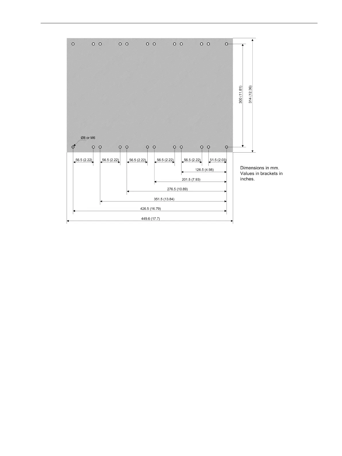
[dw_z2_bohr_1-1.vsd, 2, en_US]
Figure 6-24
Drilling Pattern of a 1/1 Surface-Mounted Device – 2nd Device Row
Technical Data
6.14 Assembly Dimensions
SIPROTEC 5, Hardware Description, Manual
247
C53000-G5040-C002-F, Edition 06.2019
50
52
Table of Contents
Main Page
Preface
3
Open Source Software
8
6 Technical Data
9
6.1 Analog Inputs
10
6.2 Supply Voltage
13
6.3 Binary Inputs
15
6.4 Relay Outputs
17
6.5 Light-Emitting Diodes in the On-Site Operation Panel
20
6.6 Communication Interfaces
21
6.7 Electrical Tests
24
6.8 Mechanical Tests
27
6.9 Environmental Conditions
28
6.10 Operating Conditions
30
6.11 Reference Conditions and Influencing Variables
31
6.12 Approvals
32
6.13 Design Data
33
6.14 Assembly Dimensions
36
6.15 Modular Device Name Plate
57
6.16 Name Plate of Non-Modular Devices (7xx81, 7xx82)
58
6.17 Name Plate, UL Approval, Base Module and 1/3 Base Module
59
6.18 Name Plate, UL Approval, Expansion Module
60
6.19 Battery
61
6.20 SDHC Memory Card
62
6.21 Display Resolution
63
Other manuals for Siemens SIPROTEC 5
Manual
490 pages
Hardware Description
302 pages
Technical Data
129 pages
Related product manuals
Siemens SIPROTEC 7SJ61
454 pages
Siemens RWF55.5
93 pages
Siemens Desigo RXC21.5
16 pages
Siemens Desigo RXC22.5
16 pages
Siemens SIPART DR20
136 pages
Siemens SIPART DR21
242 pages
Siemens SIPART DR19
94 pages
Siemens SIPART DR24
276 pages
Siemens SIPART DR22
28 pages
Siemens SIMATIC S7
336 pages
Siemens SIMATIC S5
396 pages
Siemens SIRIUS Series
18 pages