Connection Notes
Overview
Follow these recommendations:
•
Ground the device at grounding areas on the top and on the side (M4 screws) on the top and on the side
(M4 screws) with low resistance and low inductance connection. Use a conductor of at least 4 mm
2
(torque 1.2 Nm) to connect the device to protective or functional ground.
•
Establish the connections via screwed terminals. Pay attention to the labeling, permitted conductor cross-
sections, and bending radius.
•
Do not use any PIN-type terminal lugs, but only the appropriate M4 ring-type lugs.
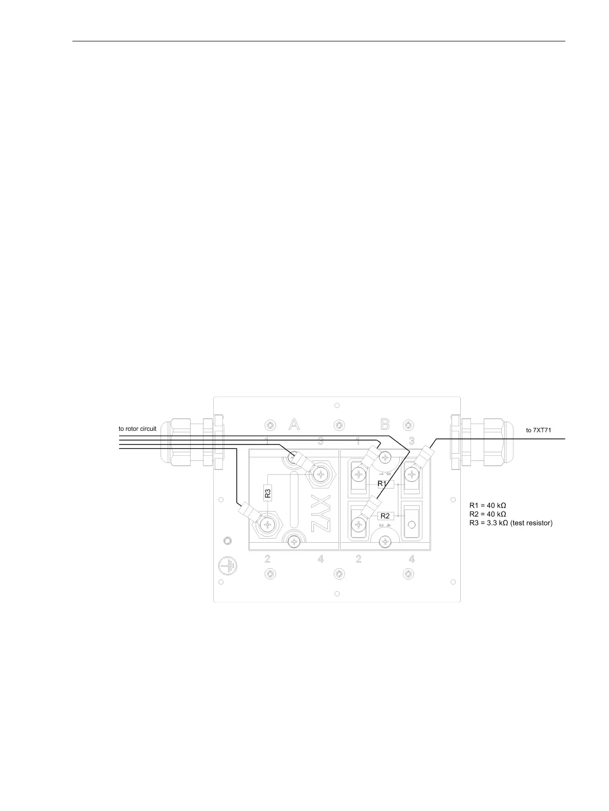
Connection Data for the Power Resistors (3.3 kΩ, 2 x 40 kΩ)
Connection via Ring-Type Lugs (M5)
•
Wire cross-section: 1.0 mm
2
to 2.6 mm
2
resp. AWG 16 to AWG 14
•
Stripping length: L = 9 mm (0.35 in) or L = 10 mm (0.39 in)
•
Permissible tightening torque at the terminal screw: 1.3 Nm (11.5 lb.in.) to 1.5 Nm (13.3 lb.in.)
•
Use copper conductors only.
Use the appropriate cable isolation for the application rated voltage (max. 2000 V RMS). The cable's permitted
continuous operation temperature must be ≥ 105 °C.
[dw_7xr8004 field cables connection, 1, en_US]
Figure 2-2 7XR8004 Field Cables Connection
2.2
2.2.1
2.2.2
7XR8004 – Resistor Coupling Unit for 7XT71
2.2 Connection Notes
SIPROTEC, Coupling Units for Generator Protection, Manual 27
C53000-H5040-C072-1, Edition 09.2018

 Loading...


