2 Order No.: 3ZX1012-0RF00-5KA1
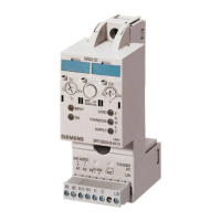
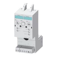
SIRIUS
Power controller
3RF29..-0KA..-0K.0
DIN EN 60947-4-3
Operating Instructions
English
su
Carry out assembly / disassembly in the order shown in Fig. I. Observe
the position of the electrical contacts (assembly step 1)
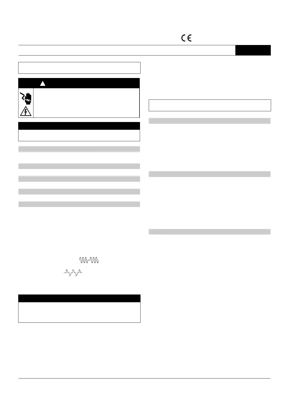
Fig. IIa (solid shaft operation), Fig. IIb (phase angle)
Fig. V: Dimensions in mm, (in)
Fig. VI
1. Connect the conductors as shown in the examples in Fig. IIa and
Fig. IIb.
2. The following setpoint options (setpoint value in % of the stored refe-
rence power rating of the loads) are available for the power control:
• If the setting switch "P" is in the 0 % position (left stop), enter the
setpoint value of 0 to 10 V (0 to 100 %) via an external analog
signal (terminal "10 V +" and "IN / 0 –"), refer to Fig. IIb.
• If the setting switch "P" is in the > 0 % position, enter the setpoint
value via the setting switch "P". It is switched on via the "IN / 0 –"
input. The analog input "10 V +" is not switched.
3. The following operating mode options are available:
• Fig. IIa: solid shaft operation
with setting switch position "t
R
" set to 0 (left stop)
(Ramp time = 0 s).
• Fig. IIb: phase angle
with setting switch position "t
R
" set to > 0 with ramp time set to
max. 10 s for the inrush current limitation. The ramp time is only
active during switch-on and refers to 100 % of the setpoint value.
4. After applying voltage to A1 / A2 (24 V AC / DC or 110 V AC), and
before the first teaching procedure, the thyristor fault (THYRISTOR)
and supply fault (SUPPLY) LEDs will flash alternatingly every 0.5 s,
since no reference power rating (100 %) has yet been stored
(taught) in the device, or if an impermissible current or voltage value
(too high or too low) has been measured (see device) during the
teaching procedure. The group signal output is not activated.
5. Carry out the first storage of the reference power rating (1st teaching
procedure) by pressing the "Test / Teach" key for more than 3 s
under normal operating conditions (voltage and current must not
exceed the specified limit values). The end of the teaching routine is
signaled by the LOAD, THYRISTOR and SUPPLY LEDs lighting up
simultaneously for approx. 1 s (Fig. III). The teaching procedure can
be repeated as frequently as desired.
The power controller can be switched on using the following options:
• Fig. IVa: By pressing the "Test / Teach" key for less than 1 s for test
purposes.
• Fig. IVb: Via the debounced control input "IN / 0 –" with the setting
switch "P" in the > 0 position (also refer to Fig. IIa).
• Fig. IVc: Via the analog input "10 V +" with the setting switch "P" in 0
position (also refer to Fig. IIb).
The "INPUT" LED will light up if one of the three ON signals are output.
The "ON" LED will light up when there is current flow.
The LEDs display the following faults:
•THYRISTOR:
Thyristor fault occurs if no current flow is detected without an ON
signal being available.
•SUPPLY:
Supply fault occurs if there is an ON signal and no current flow is
detected, or if the supply voltage is too low or not available (see
device).
The faults displayed by the LEDs are signaled as a group signal via a
NC contact (terminals 11, 12).
The operator is responsible for providing sufficient overload and short-
circuit protection for the respective applications.
Read and understand these instructions before installing,
operating, or maintaining the equipment.
DANGER
Hazardous voltage.
Will cause death or serious injury.
Disconnect power before working on equipment.
CAUTION
Reliable functioning of the equipment is only ensured with
certified components.
Assembly / disassembly
Circuit diagram
Dimension drawings
Conductor cross-sections and tightening torques
Commissioning
NOTICE
Modified settings will not take effect until the next switch-on. In
phase angle control operating mode, a reactor is required to
comply with limit values of the wire-bound interference voltage
(refer to Fig. IIb).
!
During the teaching procedure, the set ramp time "t
R
" (max. 10 s) is
fully run through. Interruptions during this period are not possible.
Operation
Fault monitoring
Overload and short-circuit protection
 Loading...