SIRIUS 3RT2 contactors/contactor assemblies
2.4 Configuration
SIRIUS Innovations
138 System Manual, 01/2011, A8E56203870002-03
/
/
/ಫ
/
/ಫ
1
8
/ಫ 1
8
/ /
8
/ಫ 1
8
/ /
˂
8
/ಫ
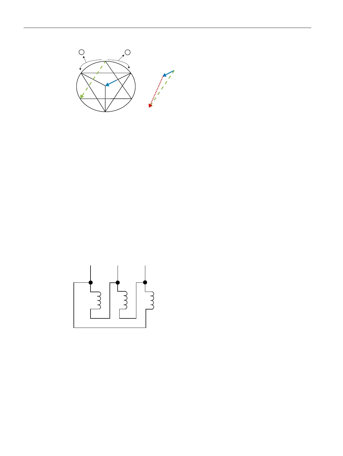
1 Rotating field
2 Rotor's overtravel during the current-free phase
Figure 2-12 Phasor diagram for star-delta switchover during clockwise rotation with motor phases
connected correctly
During the current-free changeover delay, the rotor overtravels the rotating field. Its magnetic
field induces a decaying residual voltage, entered here in the voltage phasor diagram for
phase L1: U
L1’-N
.
On switching to delta (see diagrams above), the stator winding which is conducting this
residual voltage is connected to the line voltage U
L1-L3
. Thanks to the favorable vector
position of the residual voltage U
L1’-N
and the line voltage U
L1-L3
, which are roughly rectified,
the differential voltage ΔU is relatively low. As a result, the current peak generated by this
voltage will also remain low.
Preferred wiring not used
The motor also rotates clockwise if the motor terminals are connected as follows: phase L1
to motor terminals U1 and W2, L2 to V1 and U2, and L3 to W1 and V2.
/ / /
8 9
8 9
:
:
Figure 2-13 Motor phases connected incorrectly results in clockwise rotation
The remanent and decaying residual voltage becomes effective in the stator once more. The
phase winding with phasor U
L1’-N
is now connected to the line phase U
L1-L2
on switching to
delta. However, these two voltages have totally different vectorial directions; differential
voltage ΔU is high and produces a correspondingly high switchover current peak.
A switchover from star to delta results in the phasor diagram below.
 Loading...


