SIRIUS 3RU2/3RB3 overload relays
5.5 Configuration
SIRIUS Innovations
504 System Manual, 01/2011, A8E56203870002-03
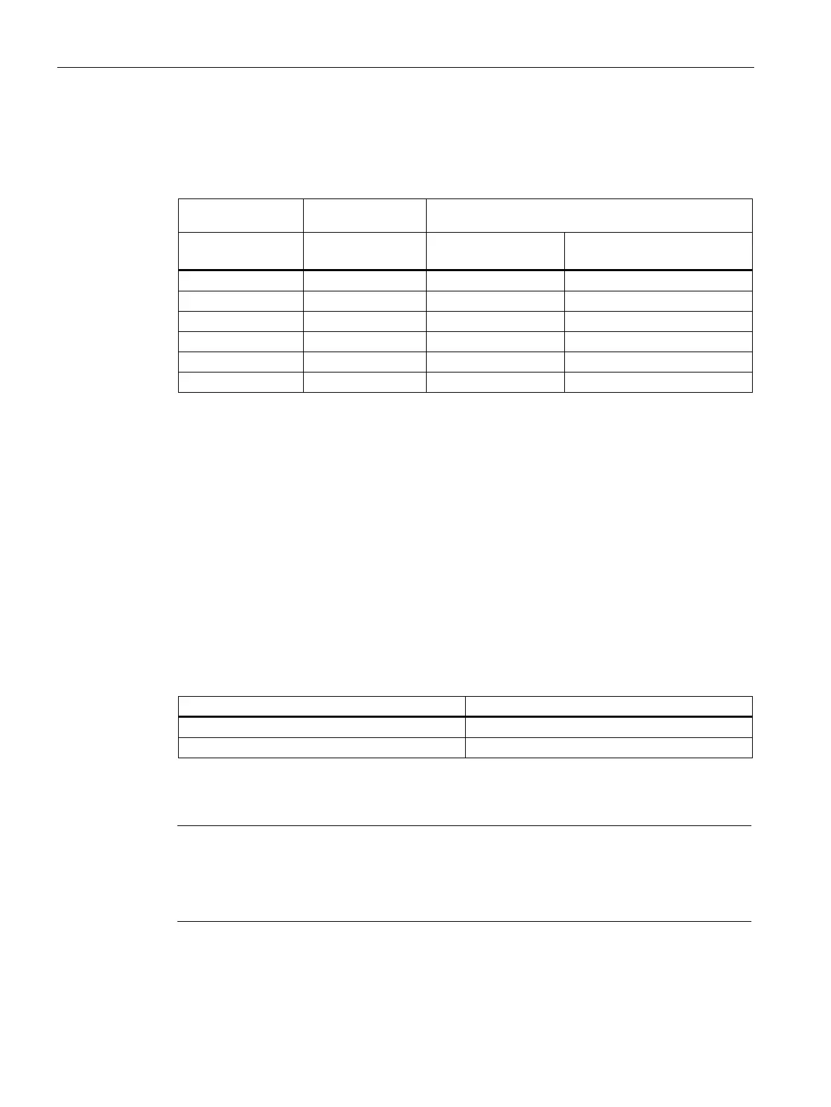
Appropriate contactors are required to protect loads. The table below provides an overview
of the assignments between overload relays and contactors, along with their power ratings.
Table 5- 9 Overload relay with contactor assemblies
Overload relay Current range Contactors
(type, size, rating in kW)
Type [A] 3RT201
S00 3/4/5.5/7.5
3RT202
S0 5.5/7.5/11/15 /18.5
3RU211
1)
0.11 … 16 ✓ -
3RU212
1)
1.8 … 40 - ✓
3RB301
1)
0.1 … 16 ✓ -
3RB302
1)
0.1 … 40 - ✓
3RB311
1)
0.1 … 16 ✓ -
3RB312
1)
0.1 … 40 - ✓
1)
If you are using the overload relays in feeders, see Technical data (Page 536)
The configuration guide titled "Configuring SIRIUS Innovations - Selection data for load
feeders in fuseless and fused designs" (order no. 3ZX1012-0RA21-1AC0) provides
information about the assembly of type-tested motor feeders according to IEC/EN 60947-4-1
with type of coordination 1 or 2.
5.5.1.2 Normal and heavy-duty starting
Normal starting
Selecting the right overload relay means considering the start time as well as the rated motor
current. The start time refers to the time required by the motor between switching on and
reaching its rated speed.
Table 5- 10 Normal starting
Designation Start time
Normal starting < 10 s
Heavy-duty starting > 10 s
Heavy-duty starting
Note
Special overload relays with corresponding tripping classes are required to protect heavy-
duty-starting motors (for the acceleration of large centrifuges, for example). In the case of
heavy-duty starting, the cables and contactors also have to be dimensioned specifically on
account of the increasing thermal load.
 Loading...


