SIRIUS 3RT2 contactors/contactor assemblies
2.7 Accessories
SIRIUS Innovations
162 System Manual, 01/2011, A8E56203870002-03
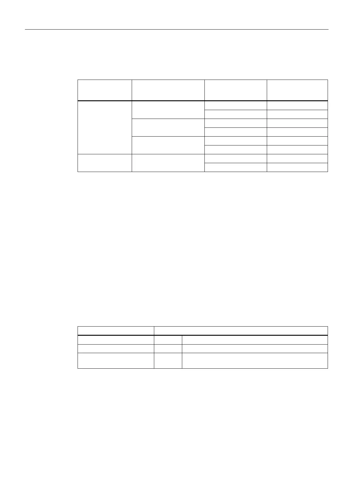
The table below depicts the size-specific auxiliary switch blocks for lateral mounting.
Table 2- 24 Laterally mountable auxiliary switch blocks
Design of the
auxiliary switch
block
Connection system Size Order number
S00 3RH2911-1DA Screw connection
S0 3RH2921-1DA
S00 3RH2911-2DA Spring-loaded connection
S0 3RH2921-2DA
S00 3RH2911-4DA
2-pole
Ring cable lug connection
S0 3RH2921-4DA
S00 3RH2911-2DE11 2-pole, solid-state
compatible
Spring-loaded connection
S0 3RH2921-2DE11
Solid-state compatible auxiliary switch blocks
Solid-state compatible auxiliary switch blocks feature two encapsulated contacts, which are
particularly well suited to switching low voltages and currents (hard gold-plated contacts) and
for operation in dusty atmospheres. The rated operational current is I
e
/AC-14 and DC-13:
1 to 300 mA, voltage: 3 to 60 V.
The solid-state compatible auxiliary switch blocks for mounting on the front are available with
screw-type, spring-loaded, and ring cable lug connections. The laterally mountable solid-
state compatible auxiliary switch blocks are available with spring-loaded connections.
Auxiliary switch blocks with overlapping contacting
Auxiliary switch blocks with overlapping contacting are available with screw-type and spring-
loaded connections. The table below shows the versions of the auxiliary switch blocks
available with overlapping contacting.
Table 2- 25 Auxiliary switch blocks with overlapping contacting
Sizes S00 and S0 Auxiliary switch version
3RH2911-1FC22 (22U) 22U 2 NO contacts + 2 NC contacts
3RH2911-1FB11 (11U) 11U 1 NO contact + 1 NC contact
3RH2911-1FB22 (11, 11U) 11, 11U 1 NO contact + 1 NC contact + 1 leading NO contact +
1 lagging NC contact
 Loading...


