SIRIUS 3RT2 contactors/contactor assemblies
2.7 Accessories
SIRIUS Innovations
System Manual, 01/2011, A8E56203870002-03
165
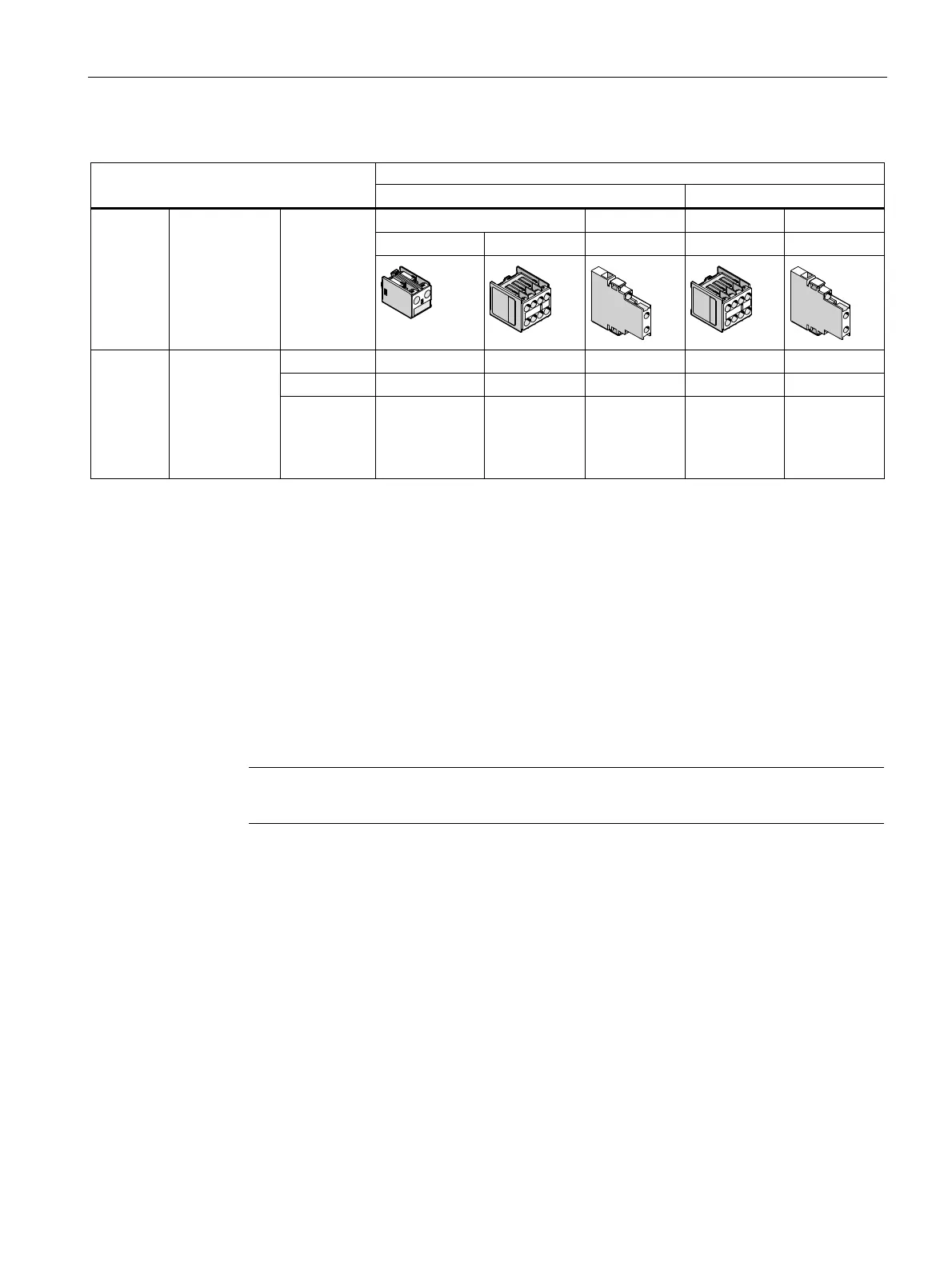
Table 2- 27 Auxiliary switch combination options (3RH2 contactor relay)
3RH21 contactor relay according to
1)
DIN EN 50005 DIN EN 50011
On the front Lateral On the front Lateral
1-pole 4-pole 2-pole 4-pole 2-pole
Size Number of
integrated
auxiliary
switches
Possible
versions
1 1 0 1 1 0
2 0 1 0 1 0
S00 2 NO contacts
and 2 NC
contacts or
3 NO contacts
and 1 NC
contact or
4 NO contacts
3 0 0 2
2)
1 0
1)
Lateral auxiliary contacts without positively driven operation
2)
1 left + 1 right
Applicable standards
The auxiliary switch blocks can be fitted according to the following standards:
● DIN EN 50005: Definition of terminal designations; however, the order of the terminal
designations and the positions of the contacts can be determined by the user.
● DIN EN 50011 for contactor relays: Defined order for terminal designations and position
of contacts.
● DIN EN 50012 for power contactors: Defined order for terminal designations and position
of contacts.
Note
Standard DIN EN 50012 is no longer valid, but is still used.
Definition: DIN EN 50005
The terminal designations for contactors are defined in DIN EN 50005, which contains
general rules. The following basic rules are defined therein for the contacts of auxiliary
circuits:
● The terminals of auxiliary contacts are identified by two-digit numbers.
● The units digit is a function number (NC contact: 1 and 2, NO contact: 3 and 4).
● The tens digit is a sequence number (all contacts with the same function must have
different sequence numbers).
 Loading...


