SIRIUS 3RT2 contactors/contactor assemblies
2.7 Accessories
SIRIUS Innovations
System Manual, 01/2011, A8E56203870002-03
213
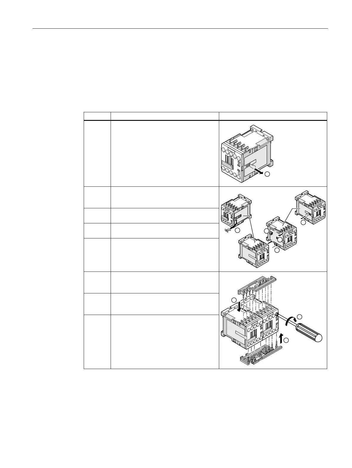
The illustration below shows example procedures for assembling the reversing contactor
assembly 3RA23 size S00 with screw-type connection. Operating instructions 1 to 5 show
how to assemble the contactors using the mechanical interlock and the connecting clips.
Assembling the reversing contactor assembly with screw-type connection - size S00
Table 2- 67 Assembling the reversing contactor assembly with screw-type connection (size S00)
Step Operating instruction Figure
1 Pull the adhesive label off the nameplate on
the right-hand side of contactor Q11.
2 Insert the mechanical interlock into the
opening on the right-hand side of the
contactor.
3 Pull the adhesive label off the nameplate on
the left-hand side of contactor Q12.
4 Insert the connecting clips into the openings
on the contactor.
5 Connect contactors Q11 and Q12 together.
6 Attach the wiring modules for connecting
the main and control current paths to the
contactors from above.
7 Attach the wiring modules for connecting
the main current paths to the contactors
from below.
8 Screw the wiring modules tight with a
screwdriver.
 Loading...


