SIRIUS 3RV2 motor starter protectors
4.4 Functions
SIRIUS Innovations
System Manual, 01/2011, A8E56203870002-03
389
The operating current increases by approx. 40% in the case of direct voltage.
1
2
PLQ
W>V@
,>$@
[,
Q
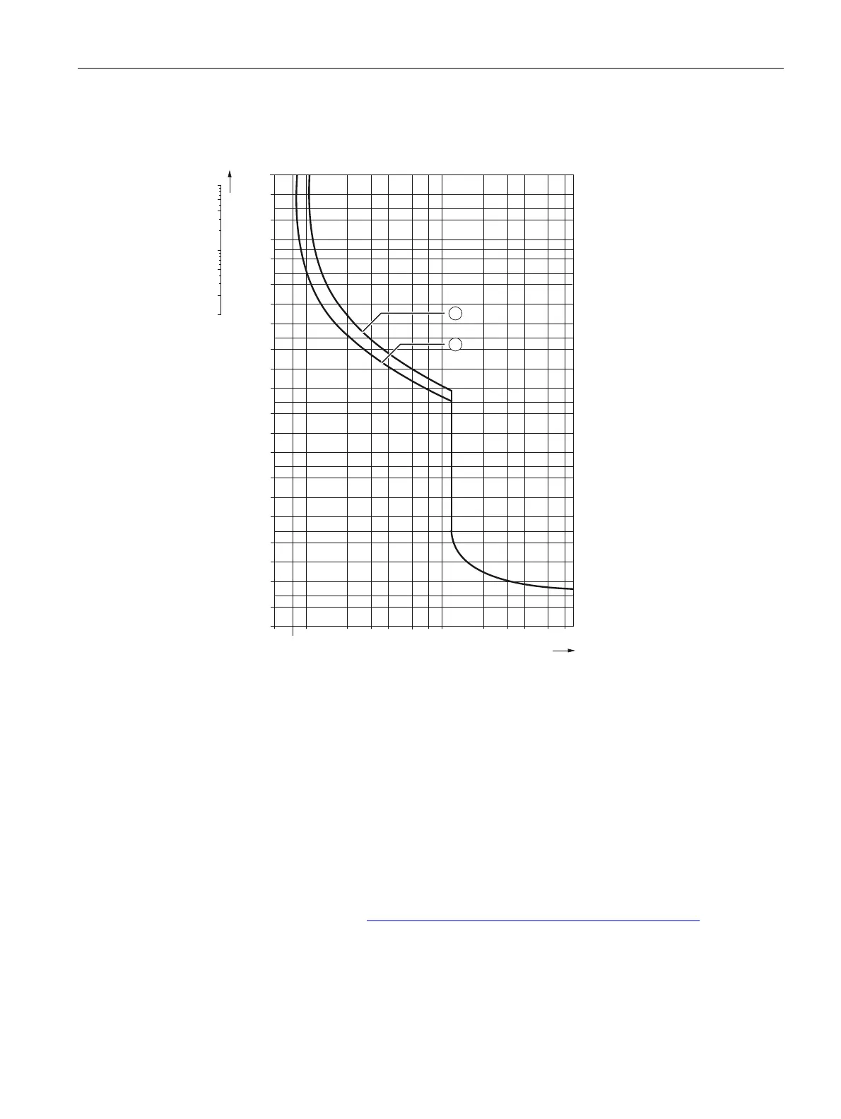
t Opening time
I Current
① 3-pole load CLASS 10
② 2-pole load CLASS 10
Figure 4-2 Schematic circuit diagram of the time-current characteristic curve for 3RV20
The characteristic curve reproduced above for the motor starter protector relates to a specific
setting range. It is, however, also valid as a schematic circuit diagram for motor starter
protectors with other current ranges.
Reference
Time-current characteristics, current-limiting characteristics, and I
2
t characteristics can be
requested on the Internet (http://www.siemens.com/automation/service&support
) via
"Technical Assistance".
 Loading...


