Operation
8.2 Connection terminals and their meanings (undelayed)
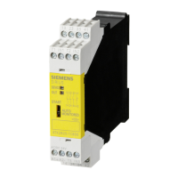
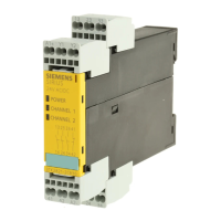
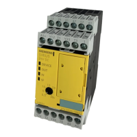
3TK2826 safety relay
20 Manual, 08/2007, GWA NEB 926 1579-02 DS 02
8.2 Connection terminals and their meanings (undelayed)
Table 8-1 Connecting terminals 3TK2826-*BB40 - undelayed enabling circuits
Connecting terminal Meaning
A1 +24V DC
A2 Chassis ground
13, 14; 23, 24; 33, 34; 43, 44 Relay enabling circuits, normally-open
51, 52 Relay signaling circuit, normally-closed (enabling circuit status)
64 Solid-state signaling circuit (feedback circuit fault), switching to P potential
74 Solid-state signaling circuit (sensor status), switching to P potential
T1, T2 Test outputs with pulsed test signals
T3 Test output with static test signal
1 Cascading input/normal switching duty
Y12, Y22 Sensor inputs, channel 1, channel 2
Y33 Start button (start after upwards and downwards edge)
Y34 Feedback circuit (checked only for "
closed"
to enable operation without feedback)
Table 8-2 Connecting terminals 3TK2826-*CW30 - undelayed enabling circuits
Connecting terminal Meaning
A1 24...240V AC/DC
A2 Chassis ground/N
13, 14; 23, 24; 33, 34; 43, 44 Relay enabling circuits, normally-open
51, 52 Relay signaling circuit, normally-closed (enabling circuit status)
63, 64 Signaling circuit, normally-open (feedback circuit fault)
T1, T2 Test outputs with pulsed test signals
T3 Test output with static test signal (+24V DC)
1 Cascading input/normal switching duty
Y12, Y22 Sensor inputs, channel 1, channel 2
Y33 Start button (start after upwards and downwards edge)
Y34 Feedback circuit (checked only for "
closed"
to enable operation without feedback)

 Loading...