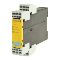
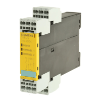
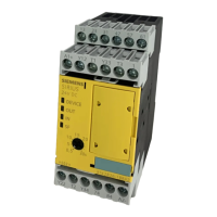
3TK2826 safety relay
Manual, 08/2007, GWA NEB 926 1579-02 DS 02
39
External circuitry
10
10.1 Sensor wiring
Parameter definitions depending on the sensor wiring
DIP switch Circuit example
1 2 3 4 5 6 7 8
Description
3TK2826-.BB4. 3TK2826-.CW3.
1 1 1 — 1 — — — 2-channel, with cross-circuit detection,
with monitored start
1 1
1 1 1 — 0 0 — — 2-channel, with cross-circuit detection,
with autostart
2 2
1 0 0 — 1 — — — Safety shutdown mat operation with cross-circuit
detection,
with monitored start
3 3
1 0 0 — 0 0 — — Safety shutdown mat operation with cross-circuit
detection,
with autostart
4 4
1 0 1 — 1 — — — NC and NO contacts with cross-circuit detection,
with monitored start
5 5
1 0 1 — 0 0 — — NC and NO contacts with cross-circuit detection,
with autostart
6 6
0 1 1 — 1 — — — Sensors with electronic outputs without cross-
circuit detection, with monitored start
7 —
0 1 1 — 0 0 — — Sensors with electronic outputs without cross-
circuit detection, with autostart
8 —
— = Not relevant
Table 10-1 Legend
DIP
switch
Meaning 1 = (ON) Meaning 0 = (OFF)
1 With cross-circuit detection Without cross-circuit detection ON
2 NC contact/NC contact evaluation NC contact/NO contact evaluation OFF
3 1 x 2-channel 2 x 1-channel OFF
Safety shutdown mat
4 Debounce time for sensor inputs 10 ms Debounce time for sensor inputs 50 ms —
5 Monitored start sensor input Autostart sensor input —
6 Monitored start cascading input Autostart cascading input —
7 Without startup testing With startup testing —
8 Without automatic startup after power
failure
Automatic startup after power failure (not
permissible in conjunction with startup testing)
—
 Loading...


