Operation
8.3 LEDs, keys and their meanings (undelayed)
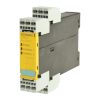
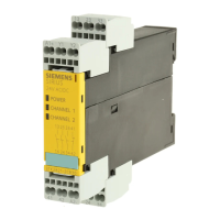
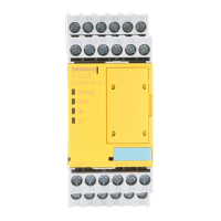
3TK2826 safety relay
Manual, 08/2007, GWA NEB 926 1579-02 DS 02
21
8.3 LEDs, keys and their meanings (undelayed)
Table 8-3 LEDs - undelayed enabling circuits
LED Status Meaning
Off No / too low supply voltage or internal fuse tripped.
Green Supply voltage in the permissible operating range
Flashing
green
Self-test during restart
Yellow Configuration mode
Flashing
yellow
Configuration error → change and enable configuration
Device
Red Device defective → Replace device
Device faulty (e.g. due to electromagnetic interference)→ Press Reset
Off Output passive
Green Output active
OUT
Flashing
green
RF not closed while start condition satisfied
Off Input passive (or switch-on condition not satisfied)
Green Input active
IN
Flashing
green
Cross-circuit at the input, simultaneity of sensors not satisfied, wire breakage during safety
shutdown mat operation, short circuit to chassis at T1/T2
Off No group fault
Red Group fault (wiring fault, cross-circuit, wire breakage in the case of safety shutdown operation,
configuration error) → Eliminate the fault and press Reset
SF
Flashing red Group fault (RF fault, simultaneity condition of the sensors not satisfied)
Off Cross-circuit detection off
Yellow Cross-circuit detection on
1
Flashing
yellow
Configuration mode, waiting for confirmation
Off NC contact / NO contact
Yellow NC contact/NC contact
2
Flashing
yellow
Configuration mode, waiting for confirmation
Off 2 x 1-channel
Yellow 1 x 2-channel
3
Flashing
yellow
Configuration mode, waiting for confirmation
Off Debounce time Y12, Y22, Y34 ~ 50 ms
Yellow Debounce time Y12, Y22, Y34 ~ 10 ms
4
Flashing
yellow
Configuration mode, waiting for confirmation
Off Autostart sensor circuit
Yellow Monitored start sensor circuit
5
Flashing
yellow
Configuration mode, waiting for confirmation
 Loading...


