Circuit diagrams/applications
13.1 Block diagrams
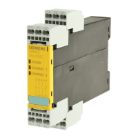
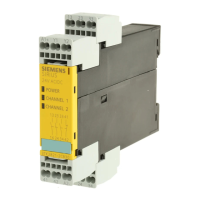
3TK2826 safety relay
66 Manual, 08/2007, GWA NEB 926 1579-02 DS 02
Typical circuit diagram of cascading with monitored start
A1
13 23
14
24
33 43
34 44
51
52
A2
A1
T3
Y33
T1
Y12
1
Y22 T2
74
Q4
ON
Y34
64
Q1
24V DC
M
Q1 Q2 Q3 Q4 H1H1 H2
.
.
.
Figure 13-6 3TK2826 - typical circuit diagram of additional safety sensor,
DIP switch 6 in position "1" = cascading input with monitored start
WARNING
Short circuit protection in accordance with IEC 60 947-5-1
The device must have an upstream fuse, 4 A gL/gG or 6 A quick-response, as short circuit
protection.
 Loading...


