Installation guidelines
Configuring SIRIUS Innovations
92 Configuration Manual, 04/2010, A8E56203880102-02
Combination
Output
Distance between feeders
Permissible installation: h = horizontal, v = vertical
Max. ambient temperature
Vibration and shock
1
Motor starter protector and
contactor
A mm h, v °C
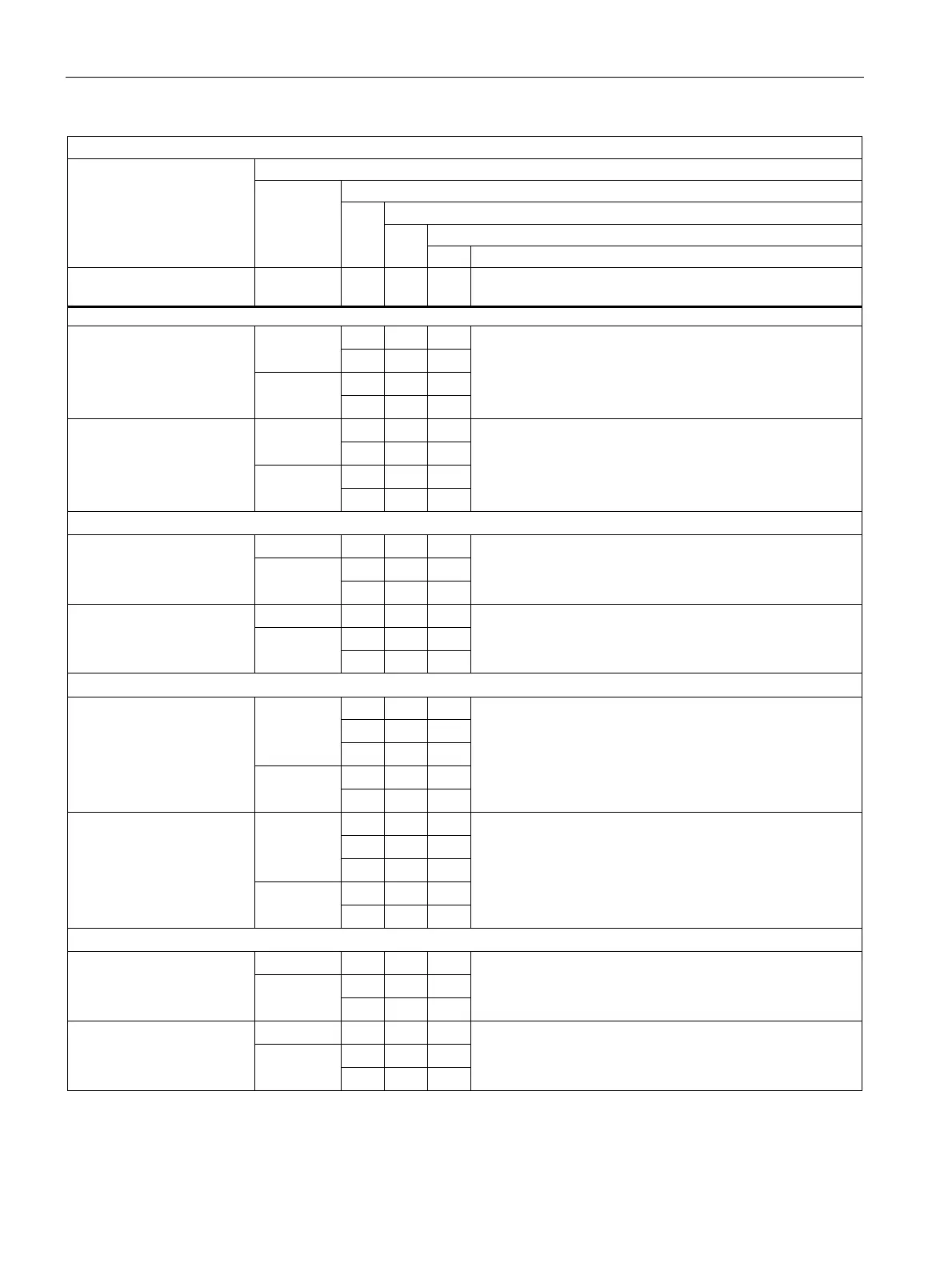
3RA22 reversing starter, screw terminal, busbar
0 h 60 ≤ 14
0 v 40
10 h 60
S00
14 … 16
10 v 40
Vibration and shock kit 8US1998-1CA10 required
0 h 60 ≤ 29
0 v 40
10 h 60
S0
29 … 32
10 v 40
Vibration and shock kit 8US1998-1CA10 required
3RA21 direct starter, spring-loaded terminal, DIN rail or wall
≤ 14 0 h, v 60
10 h 60
S00
14 … 16
0 h, v 40
Unlimited
≤ 29 0 h, v 60
10 h 60
S0
29 … 32
0 h, v 40
DIN rail adapter required
3RA21 direct starter, spring-loaded terminal, busbar
0 h 40
10 h 60
≤ 14
10 v 40
10 h 60
S00
14 … 16
10 v 40
Vibration and shock kit 8US1998-1CA10 required
0 h 40
10 h 60
≤ 29
10 v 40
10 h 60
S0
29 … 32
10 v 40
Vibration and shock kit 8US1998-1CA10 required
3RA22 reversing starter, spring-loaded terminal, DIN rail or wall
≤ 14 0 h, v 60
10 h 60
S00
14 … 16
0 h, v 40
DIN rail adapter required
≤ 29 0 h, v 60
10 h 60
S0
29 … 32
0 h, v 40
DIN rail adapter required
(already included with 3RA22)

 Loading...


