9 Commissioning the demo project
Integration of a SITOP 24V power supply in PCS 7
Entry ID: 10948108, V3.2, 01/2019
Siemens AG
2019 All rights reserved
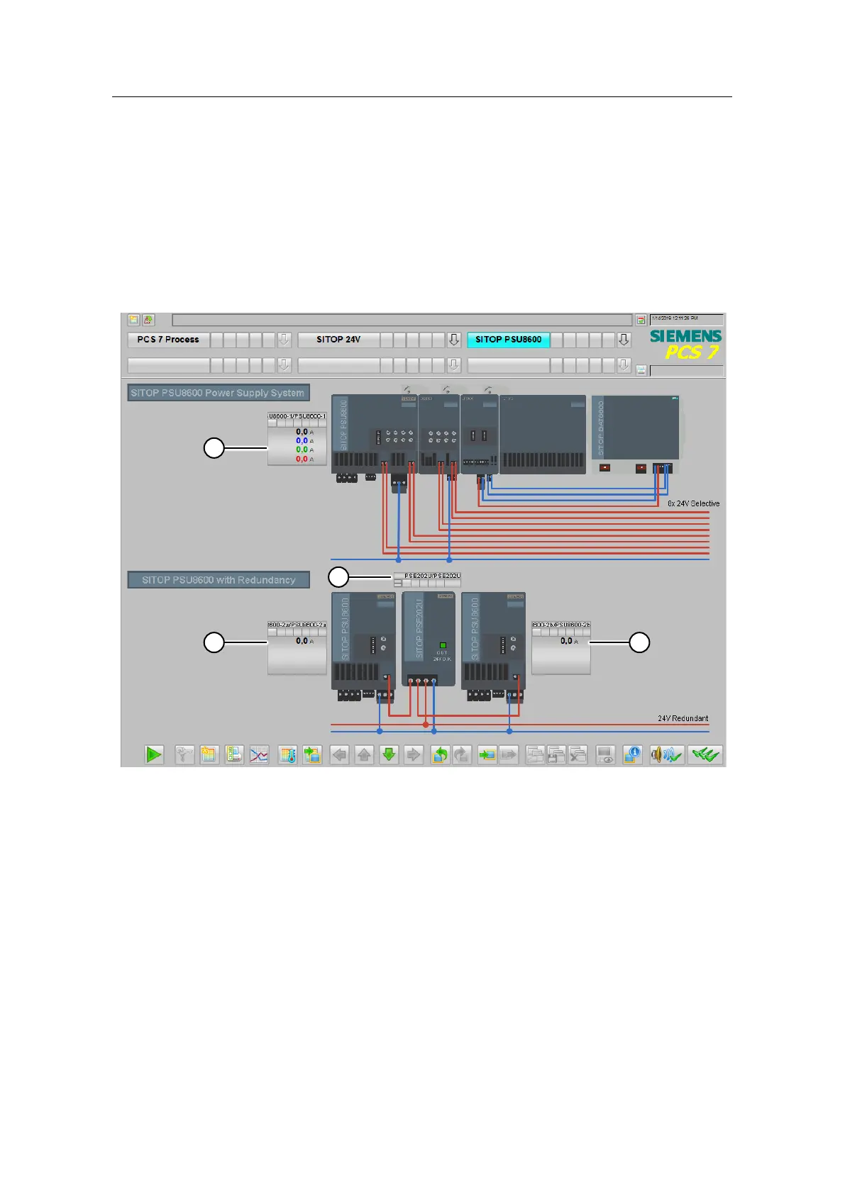
9.3 Operating the PSU8600 power supply system
9.3.1 Overview of the power supply system
After starting runtime, switch to the "SITOP PSU8600" system area. In this process
diagram the device symbols of the PSU8600 with selectivity, buffer, UPS module
and battery (1) as well as the redundantly designed PSU8600 with a 24V output
and the symbol for the monitoring of the redundancy module (3) are applied.
Figure 9-15
When monitoring via Industrial Ethernet/PROFINET, the power supply system has
its own block icon with faceplate. By installing the SITOP library, the necessary
components are copied to your system. Below, we will give you a brief description
displays on the Operator Station.
 Loading...


