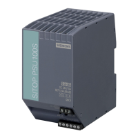
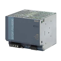
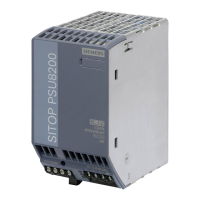
SITOP modular 1ph/2ph
Manual, 04.2018, C98130-A7548-A1-4-7629
5
Overview................................................................................................................................................. 3
1 Safety instructions ................................................................................................................................... 7
1.1 General safety instructions ....................................................................................................... 7
1.2 Safety instructions for hazardous zones ................................................................................... 7
2 Description, device design, dimension drawing........................................................................................ 9
2.1 Device description ..................................................................................................................... 9
2.2 Connections and terminal designation.................................................................................... 10
2.3 Potentiometer .......................................................................................................................... 12
2.4 Status displays and signaling ................................................................................................. 13
2.5 Change-over switch ................................................................................................................ 14
2.6 Block diagram ......................................................................................................................... 16
2.7 Dimensions and weight ........................................................................................................... 18
3 Mounting/removal ................................................................................................................................. 21
4 Mounting position, mounting clearances ................................................................................................ 23
4.1 Standard mounting position .................................................................................................... 23
4.2 Other mounting positions ........................................................................................................ 25
4.2.1 6EP1333-3BA10 ..................................................................................................................... 25
4.2.2 6EP1334-3BA10 ..................................................................................................................... 27
4.2.3 6EP1336-3BA00 ..................................................................................................................... 29
4.2.4 6EP1337-3BA00 ..................................................................................................................... 31
5 Installation ............................................................................................................................................ 33
5.1 Line-side connection ............................................................................................................... 33
5.2 Output-side connection ........................................................................................................... 35
6 Technical data ...................................................................................................................................... 37
6.1 Input ........................................................................................................................................ 37
6.2 Output ..................................................................................................................................... 39
6.3 Efficiency ................................................................................................................................. 46
6.4 Closed-loop control ................................................................................................................. 48
6.5 Protection and monitoring ....................................................................................................... 48
6.6 MTBF ...................................................................................................................................... 48
6.7 Mechanical system ................................................................................................................. 49
6.8 Accessories ............................................................................................................................. 49

 Loading...


