Installing/mounting
4.2 Installing/mounting the device
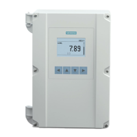
SITRANS LT500 with ultrasonic transducer inputs
Compact Operating Instructions, 02/2024, A5E52021877-AA
21
Condition
• The following have been reviewed: Basic safety notes (Page 15), and General installation
notes (Page 16).
• The correct number of cable entry holes (for this installation) are available; device was
ordered with pre-drilled cable entry holes, or customer has completed procedure Drilling
cable entry holes (Page 17).
Procedure
1. Select a place for the device and fasten the template onto the panel (use tape or tacks).
2. Drill the four fastener holes.
3. Make the cutout using the appropriate tools.
4. Place the device into the panel and insert hexagonal fasteners through bevel slots and pre-
drilled panel holes.
5. Fasten with wingnuts and hand tighten. (Use tape to hold the hexagonal heads in slots
while attaching the wingnuts.)
6. Add conduit or cable glands if applicable to application and wire as required:
– Unscrew the lid (six screws).
– Attach the conduit to the gland before connecting the gland to the enclosure.
– Unscrew the glands and attach them loosely to the enclosure. Use only approved
suitable-sized glands for watertight applications.
– Thread the cables through the conduit/glands.
To avoid interference, ensure that the power cable is kept separated from the signal
cables, and then wire the cables to the terminal blocks.
– Tighten the glands to form a good seal.
– Screw the lid in place noting recommended torque values.

 Loading...


