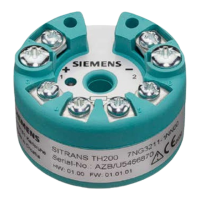
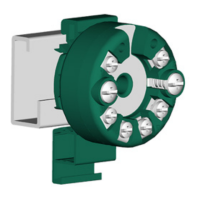
SITRANS TH/TR/TF
16 A5E32520693-01, 06/2013
Table 4-3 For T
a
≤ 85 °C (T4); T
a
≤ 60 °C (T5); T
a
≤ 45 °C (T6)
Maximum values of the auxiliary power supply and signal circuits in accordance with FISCO:
i
i
i
i
i
Table 4-4 For T
a
≤ 85 °C (T4); T
a
≤ 60 °C (T5); T
a
≤ 45 °C (T6)
Maximum values of the auxiliary power supply and signal circuits in accordance with FISCO:
i
i
i
Maximum values of the sensor circuit for Ex ia:
0
Zone 1 in type of protection "ib" - intrinsic safety
● Only connect the transmitter, in accordance with the certificate of compliance, to devices certified as intrinsically-safe.
● The transmitter must be mounted in an enclosure in order to provide a degree of protection of at least IP20 according to
EN60529
Table 4-5 For T
a
≤ 85 °C (T4); T
a
≤ 75 °C (T5); T
a
≤ 60 °C (T6)
Maximum values of the auxiliary power supply and signal circuits:
i
i
Table 4-6 For T
a
≤ 85 °C (T4); T
a
≤ 75 °C (T5); T
a
≤ 60 °C (T6)
Maximum values of the auxiliary power supply and signal circuits in accordance with FISCO:
i
i
Maximum values of the sensor circuit for Ex ia:
0
Zone 2 in type of protection "nL/ic"
● Install the transmitter in an enclosure meeting the degree of protection IP54 per EN 60529, e.g. in a type B connection
head per DIN 43729.
● Only connect the transmitter to devices that have at least been approved as certified devices of Category 3.
● Be sure to observe the respective values.
Table 4-7 For T
a
≤ 85 °C (T4); T
a
≤ 75 °C (T5); T
a
≤ 60 °C (T6)
Maximum values of the auxiliary power supply and signal circuits:
i
i
 Loading...