EasyManua.ls Logo

Siemens Sitrans LR250 - User Manual

Siemens Sitrans LR250
306 pages
Print Icon
To Next Page IconTo Next Page
Loading...
Operating Instructions
SITRANS LR250 (PROFIBUS PA)
08/2014Edition
Radar Transmitters

Table of Contents

Other manuals for Siemens Sitrans LR250

Questions and Answers

  • S
    Stephanie MataSep 16, 2025
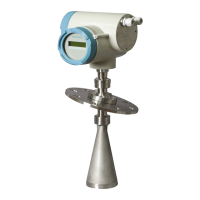
    What does it mean when my Siemens Sitrans LR250 Transmitter triggers a Maintenance Required reminder?
    • T
      Tina HudsonSep 16, 2025
      When a Siemens Transmitter triggers a Maintenance Required reminder because it is nearing its lifetime limit as defined in 4.2.3.Remaining Lifetime, replacement is recommended.
  • N
    Nicole FritzAug 25, 2025
    Why is the reading erratic on my Siemens Sitrans LR250?
    • S
      Stephen HendersonAug 25, 2025
      An erratic reading on your Siemens Transmitter can be caused by a weak echo confidence or a vortexed liquid surface. If the echo confidence is weak, you can refer to Confidence (2.5.9.1.), use Auto False Echo Suppression (2.5.10.1.) and Auto False Echo Suppression Range (2.5.10.2.), or use a foam deflector or stillpipe. If the liquid surface is vortexed, decrease the Fill Rate (2.3.8.2.), relocate the device to a side pipe, or increase the confidence threshold in Echo Threshold (2.5.7.3.).
  • A
    Ashley JohnsonAug 25, 2025
    What to do if the PLC value is not equal to the displayed value on Siemens Sitrans LR250 Transmitter?
    • S
      Shannon PonceAug 26, 2025
      If the PLC value doesn't match the displayed value on your Siemens LR250 Transmitter, verify you are looking at the right spot in the PLC. Also, ensure scaling hasn't been programmed into the PLC, as all scaling should be performed by the LR250. Finally, check the network to confirm the PLC is communicating with the LR250.
  • N
    Nicholas AtkinsAug 26, 2025
    Why is the level reading lower than the actual material level on my Siemens Sitrans LR250 Transmitter?
    • S
      samantha35Aug 27, 2025
      If the level reading is lower than the actual material level on your Siemens LR250 Transmitter, it could be because the material is within the Near Range zone or because the vessel is near empty with low dK material. To resolve this, decrease the Near Range (2.5.1.) (minimum value depends on antenna type), raise the SITRANS LR250, or ensure Algorithm (2.5.7.1.) is set to tF (First echo). If the vessel is near empty with low dK material, ensure the Material (1.2.) selection is LIQUID LOW DK, set Position Detect (2.5.7.2.) to Hybrid, and check the setting for CLEF Range (2.5.7.4.) referring to the table below Propagation Factor (2.5.3.) for recommended settings.
  • S
    Sarah HansenSep 17, 2025
    What to do if the screen is blank on Siemens Measuring Instruments?
    • S
      Stacey MasseySep 17, 2025
      If the Siemens Measuring Instruments screen is blank, it could be due to a power error. Check the nameplate rating against the voltage supply and inspect the power wiring or source. Alternatively, too much load resistance may be the cause. Try changing the barrier type, removing something from the loop, or increasing the supply voltage.
  • H
    Henry TuckerNov 28, 2025
    What does S: 0 LOE mean on my Siemens Measuring Instruments display?
    • S
      Sharon CortezNov 28, 2025
      If the Siemens Measuring Instruments display shows S: 0 LOE, it could be because the level or target is out of range. Check the specifications, check 2.2.1.6. Low Calibration Pt., and increase 2.2.4.5.1. Confidence. Another reason could be material build-up on the antenna. Clean the antenna or relocate the SITRANS LR250. Poor location or aiming, such as a poor installation or a flange not being level, can also cause this. Check to ensure the nozzle is vertical and use 2.2.5.6. Auto False Echo Suppression and check 2.2.5.7. Auto Suppression Range to ensure the nozzle protrudes from the end of the nozzle. Finally, an antenna malfunction due to temperature being too high, physical damage, excessive foam, or multiple echoes could be the cause. Check 3.14.1. Current Internal Temperature, use a ...
  • T
    Troy YoungSep 8, 2025
    What to do if Siemens Sitrans LR250 Transmitter device was unable to get a measurement?
    • R
      rgillSep 9, 2025
      If the Siemens Transmitter device can't get a measurement, consider these possible solutions: * Ensure the installation details are correct. * Ensure there is no material buildup; clean if necessary. * Adjust process conditions to minimize foam or other adverse conditions. * Correct the range calibration. The cause may be faulty installation, antenna material buildup, foaming/other adverse process conditions, or an invalid calibration range. If the fault persists, contact your local Siemens representative.
  • S
    Stephanie MartinSep 9, 2025
    What to do if Siemens LR250 Transmitter AIFB output is not equal to the displayed value?
    • M
      Michael PerrySep 9, 2025
      If the AIFB output is not equal to the displayed value, check the following: * Confirm you are looking at the AIFB Output. * Ensure AIFBs are scheduled and in Auto mode. * Ensure scaling has not been programmed into the controller: all scaling should be performed by the LR250. * Check the network to ensure the controller is communicating with the LR250.
  • W
    washingtonkristiSep 3, 2025
    What if Low Calibration Point and High Calibration Point input parameters are the same on Siemens Sitrans LR250 Transmitter?
    • D
      Donald LamSep 3, 2025
      If the Low Calibration Point (1.6.) and High Calibration Point (1.7.) input parameters are the same on your Siemens Transmitter, check the calibration settings of the device. Ensure that the settings for the High Calibration Point and Low Calibration Point are different.
  • M
    Michael StewartSep 1, 2025
    What to do if internal temperature of Siemens Sitrans LR250 Transmitter has exceeded specifications?
    • H
      hillalexanderSep 1, 2025
      If the internal temperature of your Siemens Transmitter has exceeded specifications, relocate the device and/or lower the process temperature to cool it. Inspect for heat-related damage. Note that the fault code will persist until a manual reset is performed using SIMATIC PDM or the LCD interface.

Summary

Safety Information

Safety Information

Preconditions for Safe Use

Stresses observing instructions and device symbols for safe operation.

Use in Hazardous Areas

Details qualifications required for personnel working in hazardous areas.

Installing;Mounting

Proper Mounting

Gives general notes and notices for correct mounting procedures.

Nozzle Design

Details nozzle design requirements and recommendations for various antenna types.

Disassembly

Connecting

Connecting SITRANS LR250

Gives warnings about power source and loss of protection due to installation.

Wiring Setups for Hazardous Area Installations

Outlines the three wiring options for hazardous areas.

Intrinsically Safe Wiring

Details intrinsically safe wiring and ATEX certificate information.

Instructions Specific to Hazardous Area Installations

Lists ATEX directive instructions for equipment safety in hazardous areas.

Commissioning

Quick Start Wizard via the Handheld Programmer

Provides notes and instructions for using the Quick Start Wizard.

Remote Operation

Operating via SIMATIC PDM

Introduces SIMATIC PDM as a software for device commissioning and maintenance.

Configuring a New Device via SIMATIC PDM

Explains how to configure a new device using SIMATIC PDM.

Quick Start Wizard via SIMATIC PDM

Guides through the Quick Start wizard using SIMATIC PDM.

Changing Parameter Settings using SIMATIC PDM

Explains how to change parameter settings using SIMATIC PDM.

Parameter Reference

Parameter Reference

Provides notes on parameter names, menu structure, and quick access.

Language (1.1.)

Lists parameters related to Quick Start, Language, Material, Response Rate, Units, and Operating Mode.

Material (2.3.5.)

Details Material, LOE Timer, and Calibration parameters.

Low Calibration Pt. (2.3.7.1.)

Explains Low Calibration Pt. and High Calibration Pt. parameters.

Response Rate (2.3.8.1.)

Details Response Rate, Fill Rate, and Empty Rate parameters.

Vessel Shape (2.4.1.1.)

Explains Linearization and Vessel Shape parameters.

Near Range (2.5.1.)

Covers Near Range and Far Range parameters for signal processing.

Auto False Echo Suppression (2.5.10.1.)

Details TVT Setup and Auto False Echo Suppression parameters.

Device Address (5.1.)

Explains how to set the PROFIBUS address and notes on address lock.

Service and Maintenance

Basic Safety Information

Provides safety warnings regarding impermissible repair and releasing key locks.

Maintenance and Repair Work

Outlines periodic inspection points and safety warnings for maintenance in hazardous areas.

Diagnosing and Troubleshooting

Communication Troubleshooting

Provides steps to troubleshoot communication issues, including wiring and addresses.

General Fault Codes

Lists general fault codes, their meanings, and corrective actions.

Operation Troubleshooting

Details common operating symptoms, causes, and resolutions.

Technical Data

Dimension Drawings

Appendix A: Technical Reference

Echo Processing

Explains the signal processing technology known as Process Intelligence.

Echo Lock (2.5.8.1.)

Explains Echo Threshold and Echo Lock parameters.

Auto False Echo Suppression

Introduces Auto False Echo Suppression and its purpose.

Measurement Range

Details Near Range and Far Range parameters for measurement.

Damping

Explains Measurement Response and Damping parameters.

Loss of Echo (LOE)

Explains Loss of Echo (LOE) and its conditions.

Appendix C: Communications via PROFIBUS

PROFIBUS Address

Explains PROFIBUS address identification and setting.

LCD Menu Structure

Siemens Sitrans LR250 Specifications

General IconGeneral
Accuracy± 2 mm
Power Supply10.5 to 42 V DC
Measurement PrincipleRadar
Process Temperature-40 to +80 °C
Process PressureUp to 40 bar
Output Signal4 to 20 mA HART
CommunicationHART
Enclosure RatingIP68
Housing MaterialAluminum, stainless steel

Related product manuals