Do you have a question about the Siemens SITRANS LR500 Series and is the answer not in the manual?
Provides an overview of initial setup steps and prerequisites for device operation.
Describes the manual's content and target audience for commissioning and using the device.
Lists changes between manual revisions, detailing major updates in the documentation.
Details firmware version changes for both the sensor and HMI components.
Shows compatibility between manual edition, device revision, and software versions.
Specifies how the device should be used according to nameplate and technical specifications.
Outlines steps to verify delivered items for damages and completeness against order.
Lists the components included in the product delivery package.
Warns about potential radio interference if the device is used in domestic environments.
Provides guidance on protecting plants and systems against cyber threats.
Advises using authorized sources for product information and software to prevent security incidents.
Details recommendations for safe transport and storage to maintain device protection.
States that the manual does not modify existing agreements or warranties.
Covers general safety rules and precautions before operating the device.
Explains the meaning of warning symbols present on the device.
Lists applicable safety rules, provisions, and laws for connection, assembly, and operation.
Details conformity with EU harmonization legislation like ATEX, RED, and RoHS.
Outlines conformity with UKCA marking and related UK regulations.
Warns about risks of modifications and the cancellation of warranty/approvals.
Specifies compliance with Industry Canada standards and installation requirements.
Provides notes on testing and compliance with Industry Canada limits.
Advises contacting Siemens for information on special applications or ambient conditions.
Emphasizes using the equipment only as outlined in the manual to maintain protection.
States installation must be performed by qualified personnel per local regulations.
Details qualifications for personnel and warnings for hazardous area operations.
Explains country-specific frequency settings and operating mode requirements.
Covers US installation compliance with FCC rules for Class A digital devices.
Provides Canadian and US radio approval information and conditions.
Declares compliance with EU directives and lists harmonized standards.
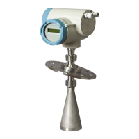
Provides a general description of the SITRANS LR500 series radar level transmitter.
Lists the types of applications the SITRANS LR500 series is designed for.
Illustrates a typical system setup with the device and related components.
Mentions supported communication protocols and directs to the Communication chapter.
Covers fundamental safety precautions for handling and installing the device.
Provides CAUTION notes on lifting and avoiding damage to the antenna.
Explains why the device is not covered by the Pressure Equipment Directive.
Details critical factors for selecting an installation location, like air supply and atmosphere.
Advises on protecting the device from direct sunlight and UV exposure.
Gives instructions and warnings for correct mounting, especially in hazardous areas.
Warns about risks associated with improper disassembly and outlines correct procedures.
Stresses user responsibility for selecting suitable materials for connections and gaskets.
Explains the concept of the sensor reference point and its variation by sensor version.
Provides guidance on nozzle location, orientation, and avoiding false echoes.
Details best practices for nozzle mounting, including length and end rounding.
Explains the necessity and method of thread sealing for process connections.
Describes the design and mounting options for the LR550 with different flanges.
Explains the use and mounting of the optional bracket for the LR550.
Mentions the optional sunshield for display protection in direct sunlight.
Covers essential safety precautions for electrical connections, especially in hazardous areas.
Highlights the risk of explosion due to improper grounding and correct connection procedures.
Provides critical safety warnings and procedures for working in explosive atmospheres.
Discusses EMC considerations and the benefit of metal enclosures and grounding.
Offers tips for enhancing immunity to interference and proper conduit sealing.
Details wiring instructions for connecting the device, including HMI connection.
Provides step-by-step instructions for connecting cables and the HMI.
Specifies the required insulation thickness for the input supply cable.
Guides on connecting the field device with the SITRANS AW050 Bluetooth adapter.
Describes the procedure for installing or replacing the Bluetooth adapter.
Addresses specific requirements and warnings for installations in hazardous areas.
Explains device nameplates and certificate numbers for hazardous area approvals.
Details the nameplate information for intrinsically safe configurations.
Discusses nameplates and information related to dust ignition protection.
Covers connection drawings and information for non-incendive installations.
Points to additional resources for hazardous area installations.
Provides crucial instructions for safe installation in hazardous areas.
Outlines specific conditions for safe use related to electrostatic charge and dust.
Provides detailed instructions for hazardous area installations based on ATEX and UK regulations.
Covers safety warnings related to commissioning, including toxic gases and hazardous areas.
Lists checks to perform before commissioning, ensuring proper installation and compliance.
Describes how to commission the device using the local display and buttons (HMI).
Details the initial startup procedure, including language and quick commissioning wizard.
Advises on preparing parameter values before using wizards.
Explains how to perform local commissioning using wizards and menu-driven parameters.
Describes the device initialization routine after power-on.
Covers using the local Human Machine Interface, including display behavior and temperature effects.
Explains the measurement and program mode displays, including navigation view.
Details how to navigate parameters, select options, and change values using the HMI.
Introduces the use of commissioning wizards for device setup.
Provides important information and steps for using the commissioning wizard.
Explains the quick commissioning wizard for simple application setup.
Describes the wizard used for demonstration purposes.
Details the wizard for preventing false echo detection.
Explains how to view and request an echo profile.
Mentions setting the device address for HART network configuration.
Recommends testing the device configuration after setup.
Describes the measurement view and the information it displays after startup.
Explains mA control parameters like saturation limits and how to verify the mA range.
Details how to configure custom applications for volume measurement using breakpoints.
Explains how to configure the device for various vessel shapes and the required dimensions.
Describes how to simulate process values, loop current, and diagnostics for testing.
Explains how to simulate process values using PDM or the HMI.
Guides on testing the application by varying process values or using simulation.
Describes how to simulate diagnostics like device status and limit monitoring.
Introduces remote operation using SIMATIC PDM.
Provides an overview of SIMATIC PDM and its functions for device management.
Details the functions of SIMATIC PDM for monitoring and configuring devices.
Advises on checking for the latest SIMATIC PDM version and updates.
Explains how to update EDD/FDI files for device compatibility.
Guides on configuring a new device using SIMATIC PDM and Quick Start wizard.
Describes the Quick Start Wizard functionality within SIMATIC PDM.
Provides important notes and prerequisites for using the Quick Start wizard.
Shows how to access and use the Quick Start wizard through SIMATIC PDM.
Details how to modify device parameters using SIMATIC PDM.
Explains how to access parameters through PDM's menu structure.
Allows manual adjustment of the TVT to avoid false echoes caused by obstructions.
Provides access to echo profile, saved profiles, TVT shaper, AFES, and echo setup.
Explains how to view, save, and manipulate echo profiles.
Allows viewing previously saved echo profiles.
Provides quick access to echo selection, filtering, and response rate parameters.
Describes setting maintenance schedules and reminders based on device lifetime.
Allows setting the mA output to report Level, Distance, or Space.
Allows inputting a simulated value to test mA connections.
Resets all parameters to factory defaults, with specific exceptions.
Reports the number of operating days and power-on times.
Describes viewing trend data for process variables.
Explains how to view device status, hardware, and maintenance information.
Lists available diagnostic functions like limit monitoring.
Describes monitoring process values and counting events based on limits.
Details the procedure for setting up process value alarms and limits.
Explains how to configure the event counter based on limit monitoring values.
Describes how to acknowledge and clear process value alarms and warnings.
Explains how hysteresis works in limit monitoring to prevent rapid switching.
Describes how overruns and underruns are counted without hysteresis.
Details how to set up and configure the trend log.
Instructions for reading and displaying trend log data.
Information on tracking operating hours for transmitter and sensor electronics.
Introduces the Quick Start function for initial device configuration.
Describes the step-by-step procedure for setting up common applications easily.
Explains the wizard used for demonstration purposes.
Details the wizard for preventing false echo detection.
Covers parameters related to device setup and configuration.
Explains how to select the primary variable (PV) for the loop current.
Describes selecting the primary variable that corresponds to the loop current.
Details selecting the secondary variable (SV) for the loop current.
Explains selecting the tertiary variable (TV) for the loop current.
Covers selecting the quaternary variable (QV) for the loop current.
Sets the type of linearization used for volume calculation.
Parameters related to sensor configuration.
Sets the units used by the device for measurements.
Sets the temperature units for the device.
Sets the maximum fill rate the device can track.
Sets the maximum empty rate the device can track.
Parameters for device calibration.
Sets distance from sensor reference to lower calibration point.
Sets distance from sensor reference to upper calibration point.
Sets level value when material is at lower calibration point.
Sets level value when material is at upper calibration point.
Sets offset to compensate for changes in sensor reference point.
Sets lower limit on measured value before offset.
Sets value for reduction in propagation velocity.
Sets offset required if electronics module is replaced.
Parameters related to the analog output.
Sets operation of loop current for HART multidrop mode.
Sets mA value for loop current in HART multidrop mode.
Sets damping/filtering of PV to smooth response to changes.
Sets process value corresponding to 4 mA loop current.
Sets process value corresponding to 20 mA loop current.
Sets lower limit for saturation range.
Sets upper limit for saturation range.
Sets lower fault current in non-safety mode.
Sets upper fault current in non-safety mode.
Defines behavior when fail-safe is initiated.
Defines fail-safe behavior when loss of echo occurs.
Sets amount of time loss of echo persists before fail-safe state.
Parameters for volume calculation.
Sets vessel shape for volume calculation.
Sets vessel height or depth for specific shapes.
Sets length of cylindrical section for specific vessel shapes.
Sets volume measurement units.
Sets maximum scaled measurement value.
Custom configuration options.
Sets maximum scaled measurement value for custom settings.
Used to enter level and output breakpoints for complex vessel shapes.
Parameters related to the local display settings.
Sets the process value shown first on display after power on.
Sets contrast level on the local display.
Used to test the device display.
Parameters related to device maintenance and diagnostics.
Parameters for identifying the device.
Displays a unique tag name for the device.
Defines a unique tag name for the device.
Displays a description for the device or measurement point.
Displays a message for the device or measurement point.
Information about the device manufacturer, product name, etc.
Displays version numbers related to the local display.
Parameters for diagnosing device status and issues.
Initiates and displays an echo profile.
Displays the status of the device.
Displays the status of the device.
Displays the status of the device.
Displays the status of the device.
Displays the status of the device.
Parameters related to signal quality.
Displays echo quality information.
Parameters for configuring echo settings like near and far range.
Sets the algorithm for echo selection.
Parameters for filtering the echo profile.
Parameters for sampling and echo lock.
Displays peak measured values.
Displays minimum electronics temperature.
Displays maximum electronics temperature.
Displays minimum distance value.
Displays maximum distance value.
Displays minimum echo signal strength.
Displays maximum echo signal strength.
Displays minimum confidence value.
Displays maximum confidence value.
Displays statistics on non-resettable peak measured values.
Configures the trend log parameters.
Sets the number of process values to log.
Sets the number of data points to capture.
Sets the interval in seconds between log entries.
Defines behavior when the log is full.
Sets the values to log.
Parameters for simulating device behavior.
Defines if simulated value is fixed or a ramp.
Sets the starting value for ramp or fixed simulation.
Sets the status of the PV to simulate.
Sets the end value for ramp simulation.
Sets the number of steps between ramp start and end.
Sets the total time for ramp simulation.
Parameters related to the current loop.
Provides procedure to simulate loop current.
Displays voltage at device terminals.
Options for resetting the device.
Restarts the device without disconnecting power.
Provides various device reset options.
Resets all recorded peak values.
Sets country-specific settings for radar signals.
Tracks configuration and calibration changes.
Displays the number of times configuration or calibration changed.
Procedures for updating firmware.
Sets analog output during firmware update.
Details the firmware update process.
Parameters related to device communication.
Sets poll ID on a HART network.
Arms device to respond to HART Command 73.
Parameters for securing the device.
Enables/disables user PIN for parameter access.
Used to change the PIN code.
Displays recovery ID for PIN recovery.
Used to enter PIN unlock key (PUK) for PIN reset.
Enables/disables user PIN and shows security status.
Sets access to device buttons.
Sets the language for the local display.
General safety notes regarding maintenance.
States the device is maintenance-free but requires periodic inspection.
Instructions for cleaning the device enclosure and display.
Warnings and procedures for maintenance and repair, especially in hazardous areas.
Safety warnings and procedures for opening the device enclosure.
Instructions for removing and installing the HMI.
Steps to disconnect and remove the HMI.
Steps to connect and secure the new HMI.
Information on how to return a product to Siemens for repair or service.
Guidance on recycling and proper disposal of the device.
Explains symbols and messages indicating device status.
Provides guidance for troubleshooting communication issues.
A detailed chart of device status symbols, their causes, and actions.
Explains information symbols that appear on the local display.
Lists information symbols and their meanings.
A comprehensive list of fault codes, their causes, and corrective actions.
Covers common operational problems and their solutions.
Addresses general operational issues.
Specific steps to troubleshoot communication problems.
Explains issues like loss of echo and fixed readings.
Guidance on aiming for optimal performance with solid materials.
Troubleshooting steps for when the reading is fixed.
Instructions for ignoring false echoes using TVT or custom shaping.
Troubleshooting steps for erratic or incorrect readings.
Details the power supply specifications.
Provides temperature de-rating tables for various protection types.
Lists recommended measuring ranges and accuracy specifications.
Describes the device's interface options like HART and HMI.
Details the analog output specifications.
Information on enclosure material and ingress protection.
Covers environmental and operational conditions.
Describes the SLOD option for gas tight feed-through.
Lists environmental specifications like altitude and humidity.
Specifies process conditions and notes on the nameplate.
Details vibration and shock resistance according to standards.
Information on the air purging system.
Details process temperature specifications based on material and seal.
Lists safety certifications and approvals for various regions.
Summarizes communication types and supported systems.
Provides temperature derating curves for different antenna types.
Graphs showing ambient vs. process temperature derating.
Graphs showing derating based on temperature and pressure.
Provides dimensional drawings and specifications for LR510.
Provides dimensional drawings and specifications for LR530.
Provides dimensional drawings and specifications for LR550.
Provides dimensional drawings and specifications for LR580.
Details how to access product documentation online.
Provides information on obtaining technical support and contacting Siemens.
Explains the fundamental principles of how the radar level transmitter works.
Describes the process of echo enhancement, selection, and verification.
Details the steps involved in processing the radar echo profile.
Explains how the device selects the true echo based on algorithms.
Describes confidence as a measure of echo quality.
Explains how to handle false echoes caused by obstructions.
Lists the algorithms used for echo selection.
Discusses loop power principles and voltage requirements.
Explains loop power and its relationship with loop voltage.
Introduces HART communication protocol and its application.
Describes the HART protocol and Process Intelligence.
Details the SIMATIC PDM software for device configuration.
Explains the role of EDD for HART device configuration.
Overview of SIMATIC PDM software.
Describes simulating process values and diagnostics in PDM.
Provides general information about SIMATIC PDM.
Advises on checking the SIMATIC PDM version and updates.
Explains how to update EDD/FDI files for device compatibility.
Information about Bluetooth connectivity.
Lists the items included in the Bluetooth adapter kit.
Guides on connecting the field device with the SITRANS AW050 Bluetooth adapter.
Step-by-step connection instructions.
Procedure for installing or replacing the adapter.
Describes connecting via the mobile IQ app.
Information about the default password.
Procedure to reset the Bluetooth password.
Technical specifications of the Bluetooth adapter.
Technical specifications of the mobile IQ app.
Dimensional drawing of the Bluetooth adapter.
Radio approval information for Canada and FCC.
Information on HART communication.
Details HART communication protocol.
Explains HART communication and its application.
Shows typical PLC/mA configuration with passive HART.
Steps to configure HART communication ports.
Information on troubleshooting HART communication issues.
| Technology | Radar (FMCW) |
|---|---|
| Output Signal | 4-20 mA HART, PROFIBUS PA, Foundation Fieldbus |
| Enclosure Rating | Type 4X/IP67/IP68 |
| Antenna Material | PTFE |
| Communication | HART |
| Approvals | ATEX, IECEx, FM, CSA |