Siemens Building Technologies
Fire Safety
P/N 315-048733-38
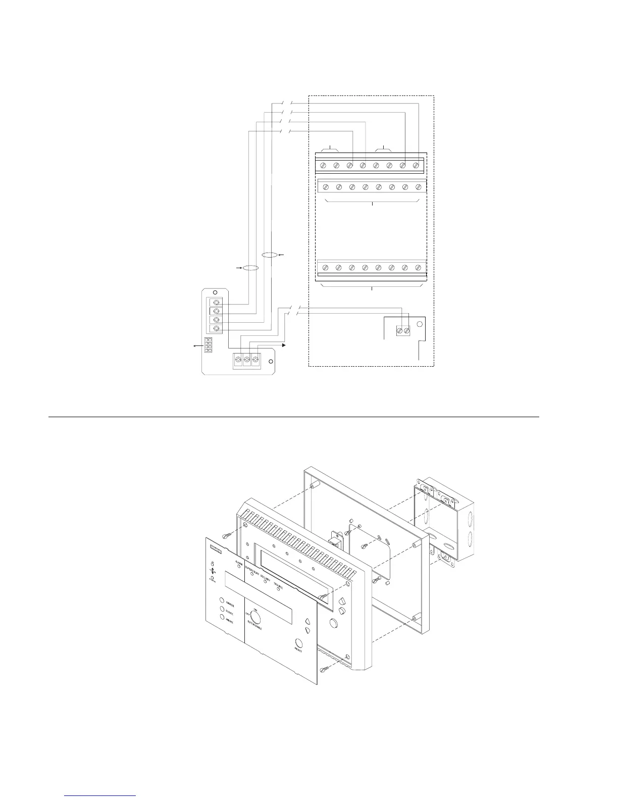
The wiring diagram in Figure 6 shows the connections from the SSD-C to the NIC-C
and PSC-12. Refer to the NIC-C Installation Instructions, P/N 315-033240 and the
PSC-12 Installation Instructions, P/N 315-033060 for additional wiring information.
SSD-TB
PAIR A
EARTH
GROUND
CABLE
TO SSD
MAIN
PAIR B
A+
A–
B–
B+
P1
PSC-12
1
+
–
2
TB3
12345678
910111213141516
17 18 19 20 21 22 23 24
DO NOT USE
DO NOT USE
DO NOT USE DO NOT USE
ONE SLOT OF CC-5
NIC-C
+
E
–
TB1
TB2
Figure 6
Wiring The SSD-C
INSTALLATION The SSD-C mounts directly onto a (user supplied) double gang or 4 inch switchbox.
Refer to Figure 7.
DOUBLE GANG BOX
3 1/2-INCHES DEEP
( A 4-INCH SQUARE BOX
2 1/8-INCHES DEEP
CAN ALSO BE USED)
MOUNTING PLATE
SSD ASSEMBLY
OVERLAY
Figure 7
Installing The SSD-C