GSM Engine TC35 Released Application Note SIM Interface
TC35-AN-01-V00.04 5/9 Version 03.00
pplication Note
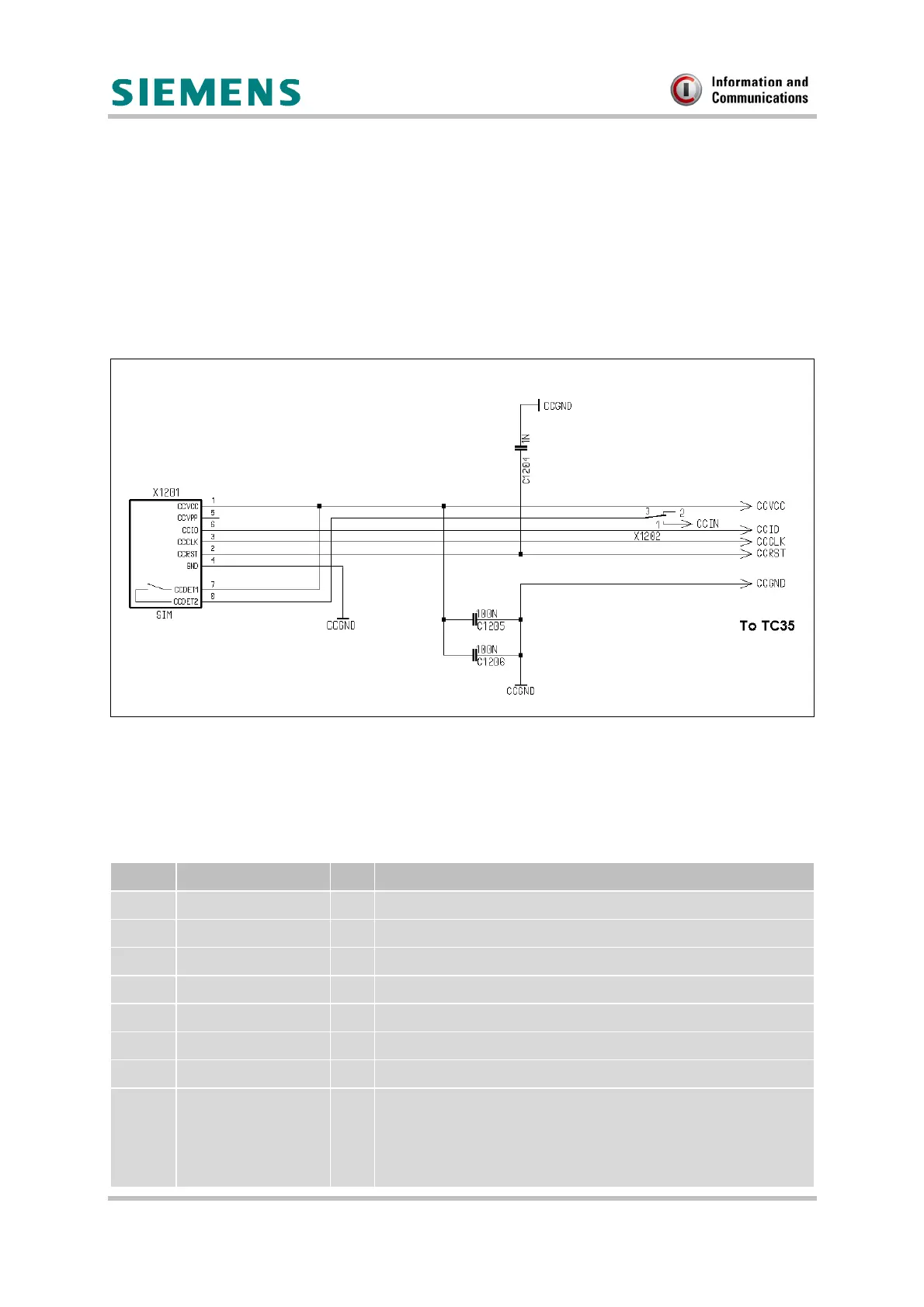
3 SIM Interface Schematic
The following schematic is a sample configuration that illustrates how the SIM card holder of
the DSB35 Support Box connects to the TC35 GSM engine.
Note :
• To ensure EMC compliance, only a maximum line length of 200 mm is permitted
between the GSM engine and the SIM card holder.
• The switch (X1202) is only for developing if you need a simulating of an empty SIM card
holder.
Figure 1: Connection of the SIM card holder
4 Pin assignment - SIM card holder
Table 1 : Pin assignment - SIM card holder
Pin no. Designation I/O Function
1 CCVCC I Supply voltage for SIM card, generated by the GSM engine
2 CCRST I Chip card reset, prompted by the GSM engine
3 CCCLK I Chip card clock
4 CCGND - Individual ground line for the SIM card to improve EMC
5 CCVPP - Not connected
6 CCIO I/O Serial data line, bi-directional
7 CCDET1 - Connect to CCVCC (see Figure 1)
8 CCDET2 Connects to the CCIN input of the GSM engine. Serves to
recognise whether a SIM card is in the holder. Removing the
SIM card during operation will immediately stop further
transmission of signals to the card to protect the card from
damage.
 Loading...