TC35i: Migration from TC35 to TC35i
PRELIMINARY
TC35_TC35i_MIG_01_V01.01 29.1.2003 Page 15 of 34
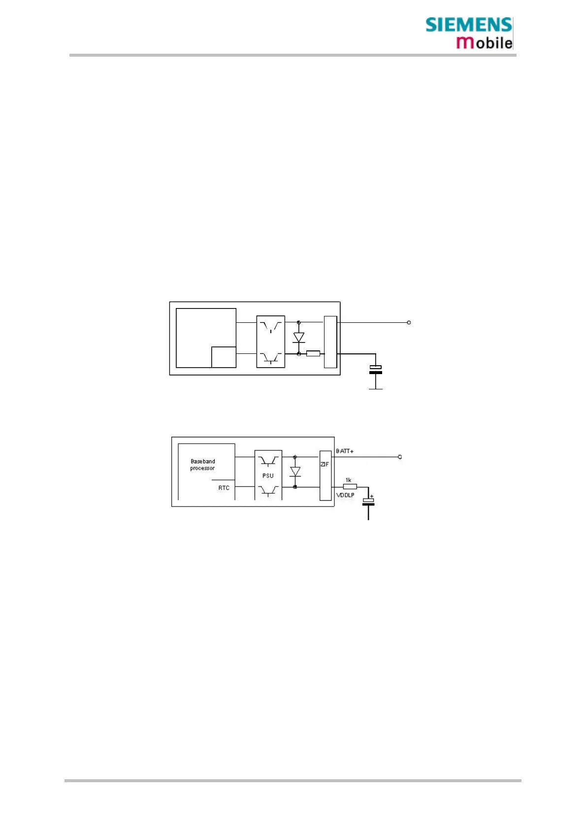
4.5 RTC backup
The internal Real Time Clock of is supplied from a dedicated voltage regulator in the power
supply ASIC which is also active when TC35 and TC35i are in POWER DOWN status. Alarm
function is included that allows waking up TC35 and TC35i without logging to the GSM
network.
On the TC35i board a serial resistor is placed next to the VDDLP line in order to limit
the input current of an empty capacitor. This eliminates the need of adding a resistor
as required in applications based on the earlier TC35 module.
On the TC35 board there is no resistor placed on the board and it should be added when
designing the GSM application
Baseband
processor
RTC
PSU
+
BATT+
ZIF
Figure 1: RTC supply from capacitor for TC35i
Figure 2: RTC supply from capacitor for TC35
4.6 Control signals
Input and Output control signals are identical with both TC35 and TC35i device.
For further information please consult the HW manual for TC35 and TC35i.
 Loading...