C
L
1.13
[28.70]
1.94
[49.28]
1.94
[49.28]
.38
[9.65]
.28 [7.11] Dia. Grounding K.O. [4 Places]
B B
B
.97
[24.64]
.97
[24.64]
1.13
[28.7]
C
L
.38
[9.65]
.10
[2.54]
B
B
B
.97
[24.64]
.97
[24.64]
1.94
[49.28]
1.94
[49.28]
7.19
[30.23]
[Door]
1.00
[25.4]
1.00
[25.4]
1.13
[28.7]
3.00
[76.2]
Door
2.81
[71.37]
8.19
[208.02]
[Door]
6.13
[155.70]
7.97
[202.44]
.85
[21.59]
2.50
[63.50]
2.50
[63.50]
5.38
[136.65]
5.00
[127.00]
5.97
[151.64]
7.69
[195.33]
C
L
.50
[12.70]
[4] .25 [6.35] Dia.
Mounting Holes
B
B
A
B
B
B
1.00
[25.4]
1.13
[28.7]
2.94
[49.28]
.85
[21.59]
30
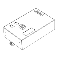
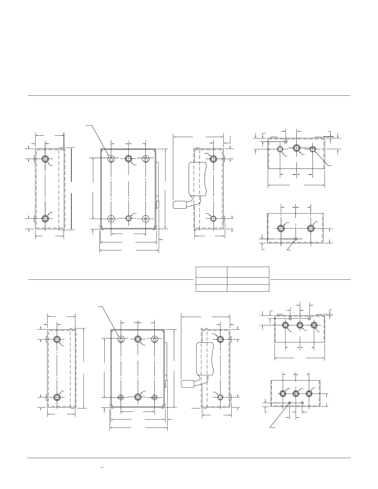
Detailed Dimension Drawings
Siemens Type VBII Safety Switches
1.00
[25.4]
1.00
[25.4]
1.13
[28.7]
3.00
[76.2]
Door
2.81
[71.37]
8.13
[206.5]
[Door]
1.00
[25.4]
.85
[21.59]
2.94
[74.68]
6.13
[155.70]
7.97
[202.44]
.72
[18.29]
1.75
[44.45]
5.38
[136.35]
1.75
[44.45]
3.50
[88.9]
5.22
[132.59]
5.94
[150.88]
C
L
.50
[12.7]
.94
[23.88]
[4] .25 [6.35] Dia.
Mounting Holes
B
B
A
A
B
B
C
L
1.13
[28.7]
1.00
[25.4]
1.00
[25.4]
.25 [6.35] Dia.
Grounding K.O.
B
B
.38
[9.65]
1.38
[35.5]
1.13
[28.7]
C
L
.38
[9.65]
.10
[2.54]
.91
[23.1]
1.63
[41.40]
1.63
[41.40]
5.44
[36.58]
[Door]
A
A
B
Figure 1
Figure 2
Type 1 (Indoor)
30 Amp General Duty (2-Pole)
30 Amp General Duty (3-Pole)
Dimensions shown in inches and millimeters [ ].
Dimensions shown accurate to
+
1/8 inch.
((
KNOCKOUT CONDUIT
CODE SIZE
A (Concentric)
.50 .75
B (Concentric) .50 .75 1.00
 Loading...