Siemens Building Technologies CE2M5324xx 15.05.2015 12
Terminals
2-pole or 4-pole terminals are used for connection of the ex-
ternal cables to the modules.
Strip-back length 5 mm
Connection capacity
rigid or flexible, 0,2 … 2,5 mm²
flexible with wire end ferrule, 0,25 … 1,5 mm²
conductor sizes 26 … 14 AWG
Multiple conductor connector (2 conductors with the same
cross-section)
rigid or flexible, 0,2 … 0,75 mm²
flexible with wire end ferrule without plastic sleeve,
0,25 … 0,34 mm²
flexible with TWIN wire end ferrule with plastic sleeve,
0,5 … 0,75 mm²
Recommended screwdriver:
0,6 × 3,5 mm
Tightening torque: 0,4 Nm
3.5 Non-detachable temperature sensors
Note: Wires must not be separated, shortened or
extended in factory-set, non-detachable temperature
sensors.
Insert the temperature sensors into the pockets, ball-valves
or T-pieces.
Seal the temperature sensors to protect against manipula-
tion.
3.6 Detachable temperature sensors
Note: If detachable temperature sensors are used
they must have their own calibration or certification of
conformity.
Note: The maximum cable length of the temperature
sensors is 10 m. Extension is not permitted.
Press the 4 side lugs of the housing cover inwards and
remove the cover.
Guide the wire of the temperature sensor from the outside
through the 2nd sleeve from the left and the return sensor
through the 3rd sleeve from the left.
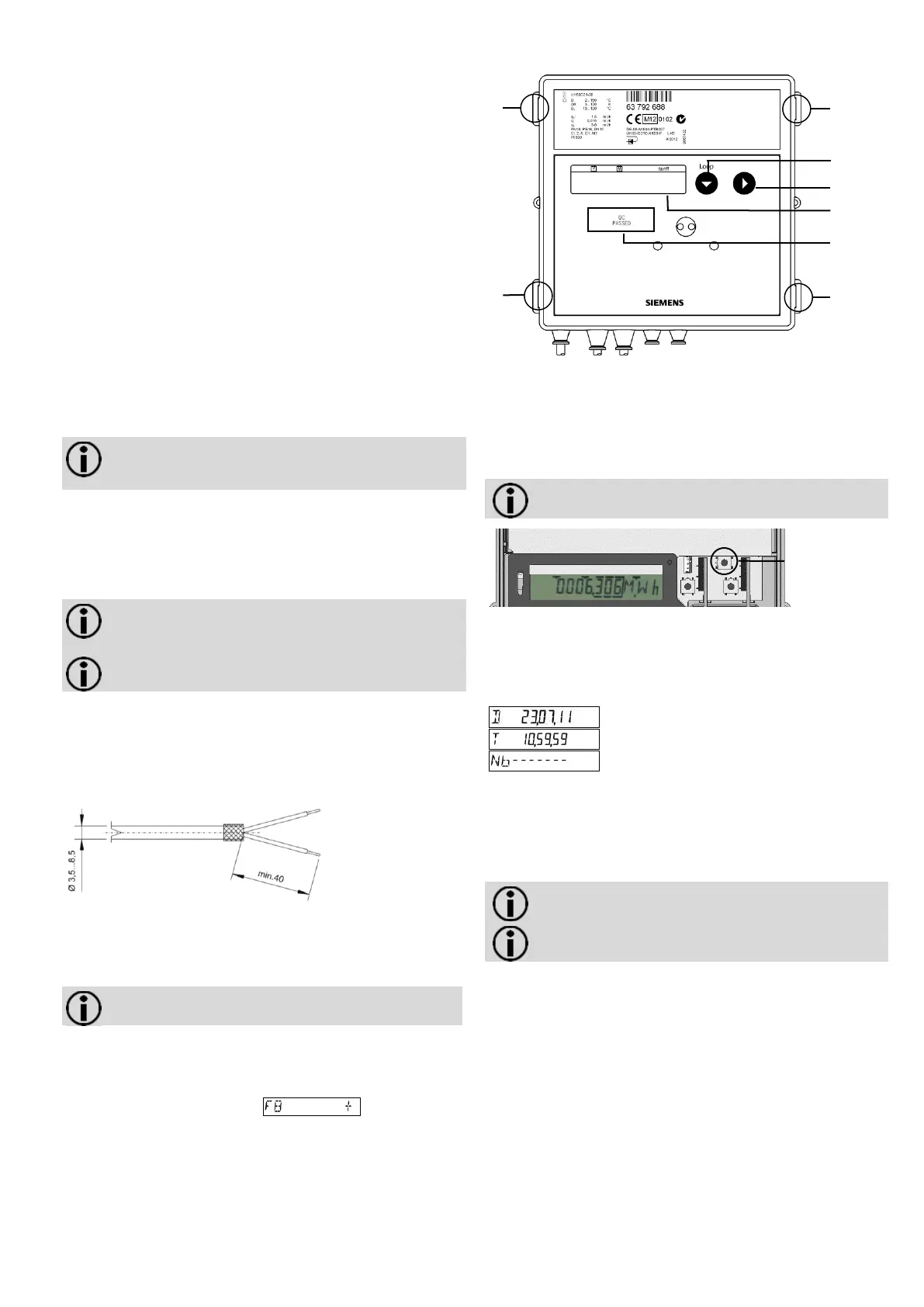
Strip both wires as in the figure 12.
wire end ferrule
Fig. 12
Connect the cores in line with the inscription printed on the
meter.
The 2-wire connection occurs on terminal 5/6 and 7/8. This
also applies to 4-wire connection).
Note: Do not connect the shielding braid on the meter
side.
Insert the temperature sensors into the pockets, ball-valves
or T-pieces.
Seal the temperature sensors to protect against manipula-
tion.
When the LCD display shows , you can reset
this error message via the parameterisation menu, as de-
scribed in chapter 4.4 „Call up parameter operation“.
Put the housing cover in position gently and press it gently
until all the lugs click into place audibly.
4. Parameterisation
Fig. 13
Note: Remove the housing cover temporarily in order
to operate the service button.
Fig. 14
4.1 Set date / time
For date and time, start meters directly with power supply unit
or battery that has been newly installed on site in the settings
menu.
Return to normal operation (manual)
Proceed as follows to set date and time:
Press button 1 until the desired value is displayed.
Press button 2. Change the values for date and time as
described in chapter 4.6 „Parameterisation“.
4.2 Parameterisation meter
Note: For battery-operation a D cell is required for
fast pulses.
Note: The parameters must be set appropriately with
the service software for the desired fast pulses.
 Loading...