18/21
Building Technologies Division CC1N7696en
20.04.2016
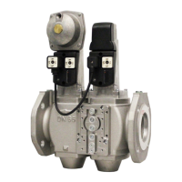
Connection examples without vent pipe to atmosphere using burner controls type LME21.xxxC... /
LME22.xxxC... with expanding flame burners
For other connections, refer to the connection diagram of the relevant burner control.
LME22.xxxC... / LME22.xxxC... with LDU11... valve proving
Before startup of burner
In the case of plants without vent pipe to atmosphere
NT
RESET
A2
Z
AL
T
T
R / W
Gpmin
STB
7101a28e/0210
LP
EK2
K1
K2/1
K3
K4K2/2
N
K5
1)
LDU11...
HR
DW
Gas
tmospheric
A1 B
E
Iar2 hr1
hr2
III V XI
MM
1)
LME21.xxxC...
LME22.xxxC...
GP
LDU LDU
GP
1) Fan motor connected to terminal 3 of the LME22.xxxC.... / LME22.xxxC...
Valve proving is started each time the system is switched on, with connection of
terminal 3, after controller ON or after lockout
If the LDU11... initiates lockout, valve proving can take up to 160 seconds. There-
fore, the maximum permissible response time of the air pressure switch is 180 se-
conds
With the LDU11…, faults during valve proving lead to lockout and, with the
LME22.xxxC.... / LME22.xxxC..., to lockout due to air pressure switch timeout (blink
code 03)
Note!
A faulty air pressure switch (switch does not make) leads to lockout (blink code 03)
on completion of the pressure switch response time of 180 seconds and can be
distinguished from lockout due to faulty valve proving only because the LDU11...
did not go to lockout
The fan motor can be connected either to terminal 3 in connection with a link be-
tween terminals 6 and 24 of the LDU11... (motor active during valve proving) or to
terminal 6 of the LDU11... (motor active on completion of successful valve proving)

 Loading...