EasyManua.ls Logo

Siemens VALVEGYR LDU11.523A27 User Manual

Siemens VALVEGYR LDU11.523A27
21 pages
To Next Page IconTo Next Page
Page #1 background imageLoading...
Page #1 background image
CC1N7696en
20.04.2016
Building Technologies Division
7
696
VALVEGYR®
Valve Proving System for
automatic Shutoff Valves
LDU11...
The LDU11... valve proving system is designed for use with shutoff valves in con-
nection with gas burners and gas appliances. In the event of inadmissible leakage,
the system prevents the burner from starting up.
The LDU11... system conforms to the requirements of EN1643 covering automatic
shutoff valves for use with gas burners and gas appliances to EN161.
The LDU11... and this Data Sheet are intended for use by OEMs which integrate the
valve proving system in their products.
Question and Answer IconNeed help?

Do you have a question about the Siemens VALVEGYR LDU11.523A27 and is the answer not in the manual?

Siemens VALVEGYR LDU11.523A27 Specifications

General IconGeneral
CategoryControl Unit
ManufacturerSiemens
Digital Inputs2
Relay Outputs2
Protection ClassIP20
Housing MaterialPlastic
Connection TypeScrew terminals
Humidity5…95 % r.h.

Summary

LDU11 Valve Proving System Overview

System Usage and Operation

Valve Proving Principle

Explains the 2-stage pressure proving principle for automatic shutoff valves.

Warning Notes and Safety Precautions

Crucial safety instructions and warnings for installation and operation.

Mechanical Design and Components

System Housing and Features

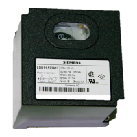
Describes the housing, lockout reset button, and internal components.

Technical Specifications

General Unit Data

Electrical, physical, and safety specifications for the LDU11... unit.

Operational Functionality

Valve Proving Test Phases

Explains the two test phases (Test1, Test2) and their outcomes.

Indicators and Control Sequence

Indicator Symbols and Meaning

Explains the symbols used on the program and lockout indicator.

Leakage Rate Calculation

Leakage Rate Formula and Example

Provides the formula and an example for calculating permissible gas leakage rates.

Electrical Connection Diagram

Diagram Legend and Components

Explains the symbols and components used in the connection diagram.

Operational Sequence Diagram

Diagram Legend and Timing

Details the timing of test phases and component operations.

Related product manuals