20/21
Building Technologies Division CC1N7696en
20.04.2016
Legend
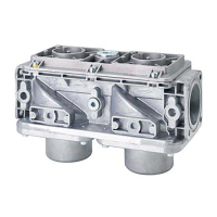
A, A1, A2 Gas valves controlled to evacuate the test space
AGK25 PTC resistor
AL Alarm signal for «leaking valve»
ar... Contacts (operating relay)
B Gas valve controlled to fill the test space
C Vent valve, normally open; closed during valve proving test from the be-
ginning of «Test1»
DW Pressure switch for valve proving test (does not replace the gas pressure
switch used to signal lack of gas)
E Safety shutoff valve, dead closed (optional)
EK Lockout reset button (internal)
EK2 Remote lockout reset button
FSV Flame signal amplifier
GP Gas pressure switch (for lack of gas)
H Main switch
ION Ionization probe
K1...4 Internal relays
hr... Contacts (auxiliary relay)
LP Air pressure switch
M... Fan («M2»: pre- and postpurging)
NT Power supply
PL Reference pressure for SKP7...
R Control thermostat or pressurestat (e.g. boiler control thermostat)
RB Pipe orifice; its diameter must be determined such that in the event of a
leaking ignition gas valve (A), the ignition flame cannot afterburn on com-
pletion of the second safety time so that presence of the main flame can-
not be simulated
SB Safety limit thermostat
STB Safety limit thermostat
T Delay off time relay; the time should be set to approx. «t16» (min. «t7»...
max. «t10») of the burner control
W Limit thermostat or pressure switch or pressure limiter
Z Ignition transformer
t7 Interval between start command and power at terminal 7 (start delay for
«M2»)
t10 Interval from start to the beginning of the air pressure check, excluding
running time of air damper
t16 Interval until OPEN command for the air damper is given
 Loading...