Do you have a question about the Siemens XTRI-S and is the answer not in the manual?
The Siemens XTRI-S, XTRI-D, and XTRI-R are addressable interface modules designed to integrate various devices into a fire alarm system loop. These modules are crucial for extending the functionality of fire alarm control panels by allowing the connection of conventional devices, such as shorting devices, to the addressable loop. The XTRI-S, XTRI-D, and XTRI-R modules are part of the Siemens Industry, Inc. product line, offering a reliable solution for fire safety management.
These modules serve as an interface between the addressable fire alarm control panel and conventional devices. They are designed to monitor the status of connected devices and report this information back to the control panel. The XTRI-S, XTRI-D, and XTRI-R modules support both polarity insensitive and isolator modes, providing flexibility in system design and wiring.
In polarity insensitive mode, the module can be wired without regard to the polarity of the connection, simplifying installation. This mode is particularly useful in situations where wiring errors might occur or where the existing wiring infrastructure is not polarity-sensitive.
The isolator mode, on the other hand, allows the module to isolate a short circuit on the line in front or behind the module. This feature is critical for maintaining the integrity of the fire alarm loop. In the event of a short circuit, the isolator module will segment the loop, preventing the entire system from being compromised and ensuring that other parts of the system remain operational. This enhances the reliability and resilience of the fire alarm system.
The XTRI-S, XTRI-D, and XTRI-R modules are available in three models, each with specific functionalities. The XTRI-S (P/N S54370-B3-A1) and XTRI-R (P/N S54370-B1-A1) are designed to monitor a normally open or closed dry contact. This means they can detect changes in the state of a connected device, such as a smoke detector or a manual pull station, and transmit this information to the control panel. The XTRI-S can also monitor and report the status of the contact, while the XTRI-R incorporates an addressable Form C relay, allowing for control of external devices.
The XTRI-D (P/N S54370-B2-A1) is a dual input module that supervises and monitors two sets of dry contacts. This dual input capability makes it suitable for applications where multiple devices need to be monitored from a single module, optimizing wiring and installation costs.
Operating Voltage:
Max Average Current (RMS):
Wiring Specifications:
Relay Contact Ratings (for XTRI-R):
Supervised Switch Ratings:
End of Line (EOL) Resistor:
Device Capacity:
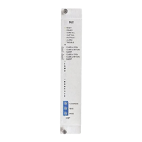
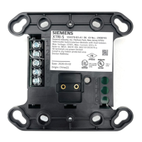
Mounting: The XTRI-S, XTRI-D, and XTRI-R modules are designed for easy installation into a standard 4-inch square box or a double gang 4-inch switchbox. The module fastens to the switchbox with two screws provided. A red LED on the module blinks to indicate an off-normal input switch position and/or an internal relay transfer, providing visual status feedback.
Programming Holes: The modules feature programming holes that allow for easy connection of the DPU Programmer/Tester. This tool is used to program the XTRI address, ensuring proper communication with the fire alarm control panel. The design ensures that the plug from the DPU Programmer/Tester can be inserted into the holes at either direction, simplifying the programming process.
Wiring Switches and EOL: The modules support both normally closed and normally open programmable switches. For normally closed switches, the EOL resistor is connected in series with the switch. For normally open switches, the EOL resistor is connected in parallel with the switch. This flexibility allows for integration with a wide range of conventional devices.
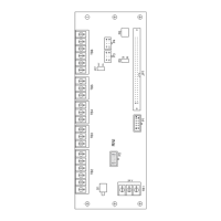
Power Limited Wiring: All power limited wiring must enter the outlet box separately from the electric light, power, Class 1, or non-powered limited fire protection signaling conductors. For the XTRI-R, wiring to terminal block positions 1, 2, 3, 4, and 5 must enter the outlet box separately from terminals 6, 7, and 8. This separation is crucial for maintaining electrical safety and preventing interference.
Wiring at the Terminal Blocks: The modules provide clear terminal blocks for wiring connections. Power limited wiring connects to positions 1, 2, 3, 4, and 5, and is power limited. Non-power limited wiring connects to positions 6, 7, and 8, and is considered non-power limited.
Ground Shield: The ground shield of the device line ONLY at the specified location on the Control Panel. Non-shield cable can be used for input.
EOL Device: The EOL device must be a 470 ohm, 1% 1/2W resistor for wire open supervision, which comes with the product.
Polarity Insensitive Mode Wiring: The wiring diagrams for polarity insensitive mode (Figures 8, 10, 12) illustrate how to connect the XTRI modules to the addressable loop and to the next addressable device. These diagrams show the connections for Line 1, Line 2, and the monitored addressable device.
Isolator Mode Wiring: The wiring diagrams for isolator mode (Figures 9, 11, 13) demonstrate how the XTRI modules function as isolators within the loop. These diagrams show how the module segments the loop to isolate faults, ensuring continued operation of other parts of the system.
Module Status LED: The module features a multi-color LED that indicates its operational status, aiding in troubleshooting and maintenance.
Troubleshooting: The manual provides guidance on how to connect the DPU Programmer/Tester to the XTRI module for programming and troubleshooting. This tool helps in identifying and resolving issues related to module addressing and communication.
Periodic Checks: Regular checks of the module status LED and wiring connections are recommended to ensure proper operation. Any changes in LED behavior or wiring integrity should be investigated promptly.
Replacement: If the module LED shows no flashes, it indicates a power issue or that the module needs to be replaced. In such cases, the module should be replaced with a new one to maintain system functionality.
Compliance: The device generates, uses, and can radiate radio frequency energy and if not installed and used in accordance with the instructions manual, may cause interference to radio communications. It has been tested and found to comply with the limits for a Class A computing device pursuant to Part 15 of FCC Rules, which are designed to provide reasonable protection against such interference when operated in a commercial environment. Operation of this equipment in a residential area is likely to cause interference in which case the user at his own expense will be required to take whatever measures may be required to correct the interference. This information is crucial for ensuring the device operates within regulatory guidelines and for addressing any potential interference issues.
| Brand | Siemens |
|---|---|
| Model | XTRI-S |
| Category | Recording Equipment |
| Language | English |