Ionics Instruments 2004 Page D - 8 DLM 30007-08 Rev. A
Software Configuration
It is necessary to configure the binary inputs following a firmware upgrade.
Follow these instructions to configure inputs and select proper polarity.
The purpose of the Binary/Digital Input Module is to send a binary/digital signal
to the analyzer that will change to operating mode to a PAUSED state.
To wire the analyzer for binary/digital inputs:
1. Connect the flow switch to the provided terminal block on the
Binary Switch Module located on the Auxiliary Port, which is on
the left side of the analyzer.
2. Use a continuous closure contact system only. Applying voltage
to the Binary Switch Module may damage the analyzer.
3. Use either opening in the Binary Switch Module. There is no
polarity on the terminal block.
To setup the analyzer for binary/digital input:
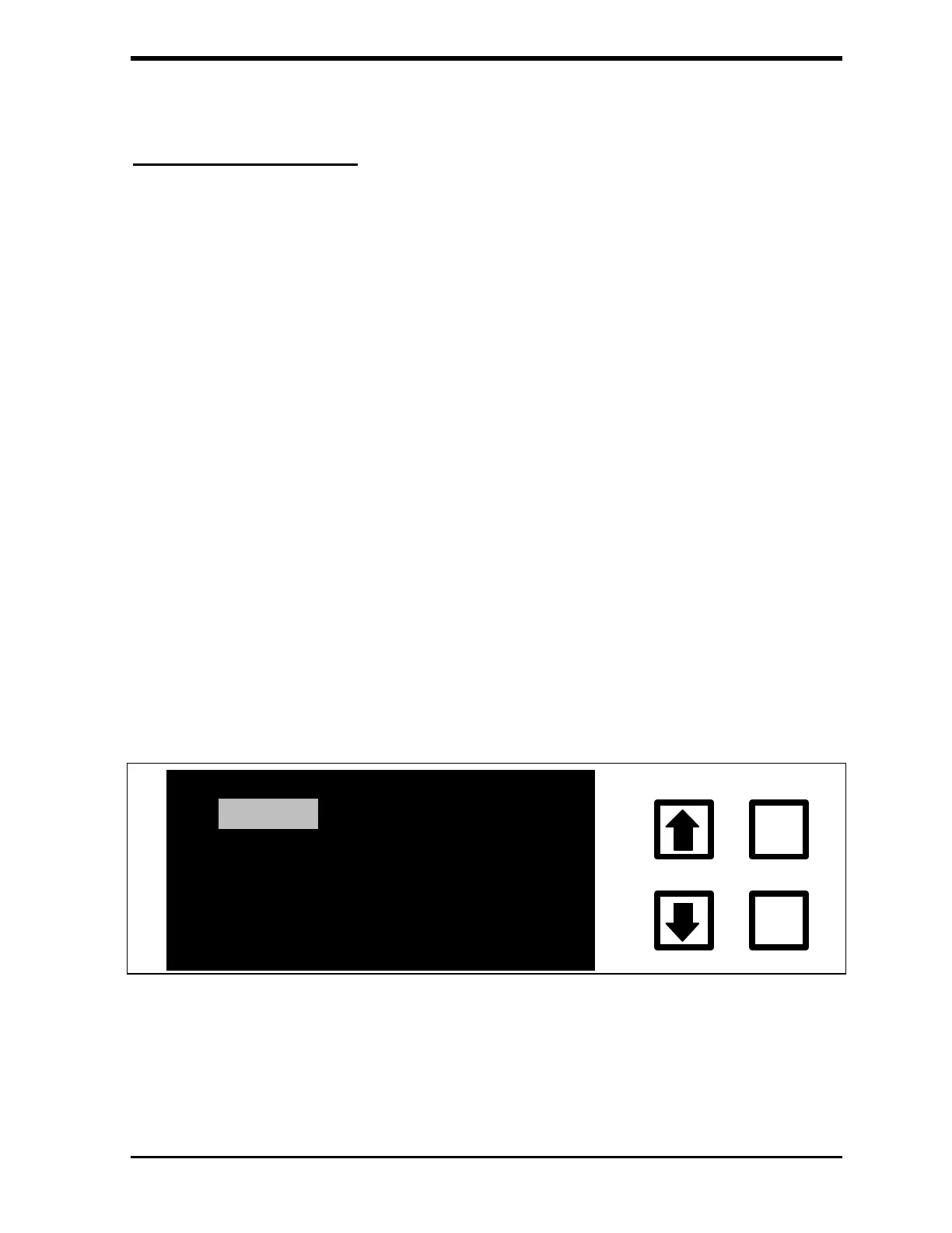
1. From the MAIN menu, scroll with the arrows ( or ) to select
SETUP and press ENTER.
HISTORY
SETUP
ERRORS
MAINTENANCE
CALIBRATE
ENTER
CLEAR
START TOC
FIGURE D-4: MAIN Menu
2. The SETUP menu is displayed: