Do you have a question about the Sieza Peridect+ and is the answer not in the manual?
Details the primary function and application scope of the PERIDECT+ system for perimeter security.
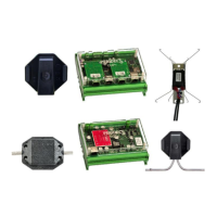
Outlines the basic components and optional supplementary elements that form the PERIDECT+ system architecture.
Explains the detection line, comprising DSP+ detectors and interconnecting cables, and its available versions.
Describes the standard detection perimeter version, its casing, cable connections, and installation considerations.
Details the antivandal detection line version, emphasizing enhanced resistance to cable damage and protection features.
Covers the hidden detection version, designed for discreet installation within fence posts for unidentifiable security.
Provides step-by-step instructions for planning detector addressing and connecting detection lines on the fence.
Introduces the central control unit responsible for processing signals and managing system actions.
Explains the various terminal board connections for the CUP+ control unit, including power, data, and outputs.
Describes the LCP+ line controller, which manages communication and power for modules along the detection line.
Details the terminal board connections for the LCP+ line controller, including power and communication interfaces.
Explains the meaning of LED indicators on the CUP+ and LCP+ units for operational status and communication.
Introduces the LIP+ module for connecting external devices, featuring double-balanced inputs.
Describes the LPP+ module, designed to enhance resistance to electromagnetic interference and voltage surges.
Introduces the I/O module for controlling external devices and indicating system statuses via ETH or RS485.
Details the terminal board connections for the IOP+ module, covering inputs and relay outputs.
Explains the LSP+ module's function in isolating parts of a detection line experiencing electrical issues.
Presents a visual overview of the PERIDECT+ system architecture and component interconnections.
Provides detailed technical specifications for the CUP+ control unit, including voltage, consumption, and dimensions.
Lists the technical specifications for the LCP+ line controller, covering supply, consumption, and operational limits.
Details the technical specifications for the LIP+ line input module, including power, consumption, and inputs.
Outlines the technical specifications for the DSP+ detection sensor, covering power, consumption, and protection.
Provides technical specifications for the LSP+ line separator module, including power, consumption, and protection.
Lists the technical specifications for the IOP+/LAN I/O module, including voltage, consumption, and operating range.
Details the technical specifications for the IOP+/RS485 I/O module, covering supply, consumption, and temperature range.
Outlines the technical specifications for the IOP+/EXP expansion module, focusing on consumption and operating range.
| Brand | Sieza |
|---|---|
| Model | Peridect+ |
| Category | Security System |
| Language | English |