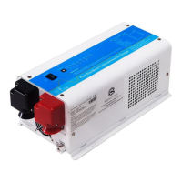
Allow at least 1 inch of clearance around the inverter for air flow. Make sure that the air can circulate freely
around the unit.
Fan noise level <60db at a distance of 1m
2.5.10 DIP Switches
On the DC end of inverter, there are 5 DIP switches which enable users to customize the performance of the
device to suit the specific configuration.
Low Battery Trip Volt:
Deep discharge of the lead acid battery and many others leads to high losses in capacity and early aging.
Thus discharging a battery properly according to its characteristics is getting more and more important.
In different applications, different low voltage disconnection level is preferred. For example, for solar and
renewable energy application, users many intend to have less DOD(depth of discharge) to prolong the
battery cycle life. While for mobile or emergency power backup applications, users many intend to have
more DOD to reduce battery capacity and on board weight.
Our inverter chargers are designed with circuit to shut off inverter at adjustable low battery cutoff voltage
set points.
For 12VDC model in AC priority mode, the Low Battery Disconnect Volt is set at 10.0VDC at position 0 by
default. It can be customized to 10.5VDC using SW1, this is to prevent batteries from over-discharging
while there is only a small load applied on the inverter.
This low battery cutout voltages are bought up by 0.5 and 1.0 volt in Battery priority mode, giving the
batteries more protection.
*2 for 24VDC, *4 for 48VDC
AC Input Range:
There are different acceptable AC input ranges for different kinds of loads.
For some relatively sensitive electronic devices, a narrow input range of 184-253VAC (100-135V for
120VAC models) is required to protect them.
While for some resistive loads which work in a wide voltage range, the input AC range can be customized to
154-253VAC (90-135V for 120VAC models), this helps to power loads with the most AC input power

 Loading...