AP04 Datum 08.06.2011 Art.Nr. 84211 Änd. Stand 189/11 7
User Information
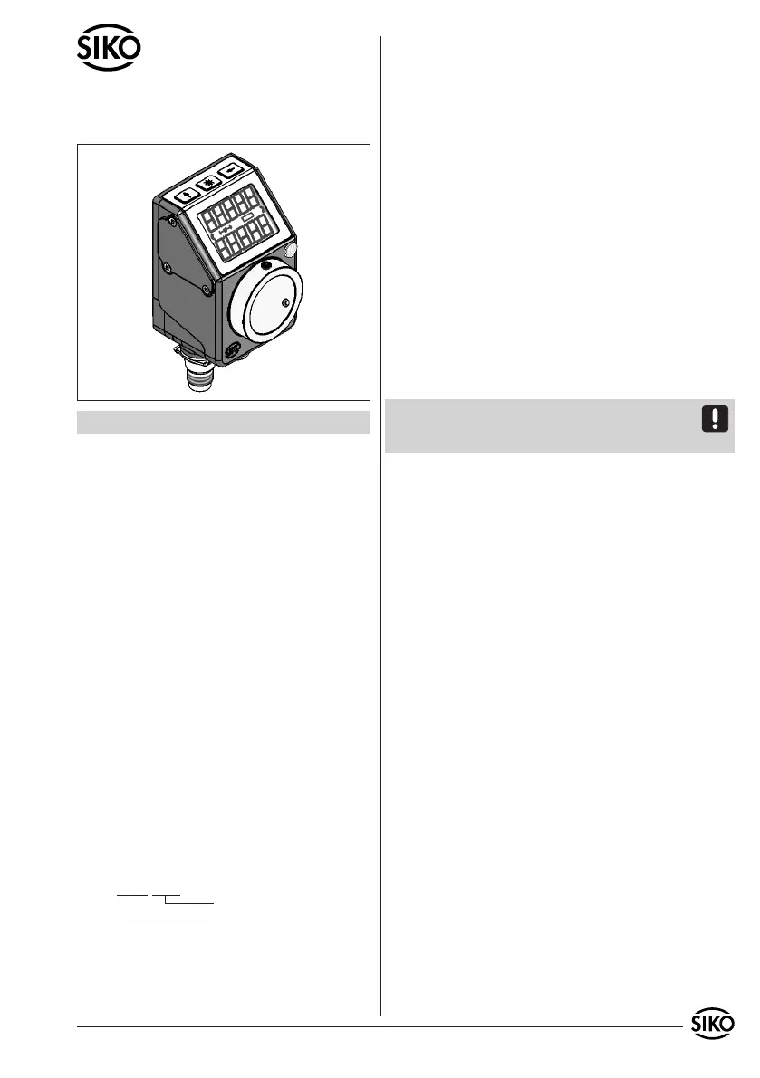
AP04
Absolute/Electronic Positon Indicator
ENGLISH
1. Warranty information
• In order to carry out installation correctly, we
strongly recommend this document is read very
carefully. This will ensure your own safety and the
operating reliability of the device.
• Your device has been quality controlled, tested
and is ready for use. Please respect all warnings
and information which are marked either directly
on the device or in this document.
• Warranty can only be claimed for components sup-
plied by SIKO GmbH. If the system is used together
with other products, the warranty for the complete
system is invalid.
• Repairs should be carried out only at our works.
If any information is missing or unclear, please
contact the SIKO sales sta.
2. Identification
Please check particular type of unit and type
number from the identification plate.Type number
and the corresponding version are indicated in the
delivery documentation.
e. g. AP04-0023
version number
type of unit
3. Intended use
The AP04 position indicator is a high-precision
measuring instrument. It serves exclusively for the
acquisition and output of position values, for pro-
cessing and providing measured values as electrical
output signals for an upstream control as well as
for the indication of target values and positioning
aids. The AP04 must be used exclusively for these
applications.
• Conversion or alteration of the device not approved
by SIKO is forbidden for safety reasons.
• Observe the operation and installation instructions
specified in this User Information.
• Refrain from any operation that may compromise
safety with the device.
4. Installation
The unit should be used only according to the pro-
tection level provided. Protect the unit, if necessa-
ry, against environmental influences such as spra-
yed water, dust, knocks, extreme temperatures.
Attention: The unit should not be exposed to elec-
tromagnetic fields. Especially do not mount close to
adhesive or other permanent magnets.
Before mounting the AP04, the enclosed self-adhe-
sive gasket (microcelluar rubber) must be stuck on
the bearing support or distance plate, respectively.
This helps to level possible unevenness and pre-
vents dust from invading the bearing.
Slide AP04 onto the solid shaft, insert torque pin
into the prebored mounting hole and use grub
screw M3 to fix the AP04's hollow shaft to the
machine's solid shaft (see fig. 1).
Please note: Do not tighten the grub screws with
more than 0,2 Nm!
• Ensure sliding fit between solid shaft and AP04.
• Ensure accurate shaft alignment and mount the
AP04 without force. Do not exceed the values
for the maximum axial and radial shaft load. If
the shaft is not correctly aligned, strain on the
bearings will result, which may cause overheating
and irreparable damage.
• Ensure that AP04 does not jam and that it is moun-
ted without strain.
• Knocks on the unit should be avoided!
 Loading...