8 AP04 Datum 08.06.2011 Art.Nr. 84211 Änd. Stand 189/11
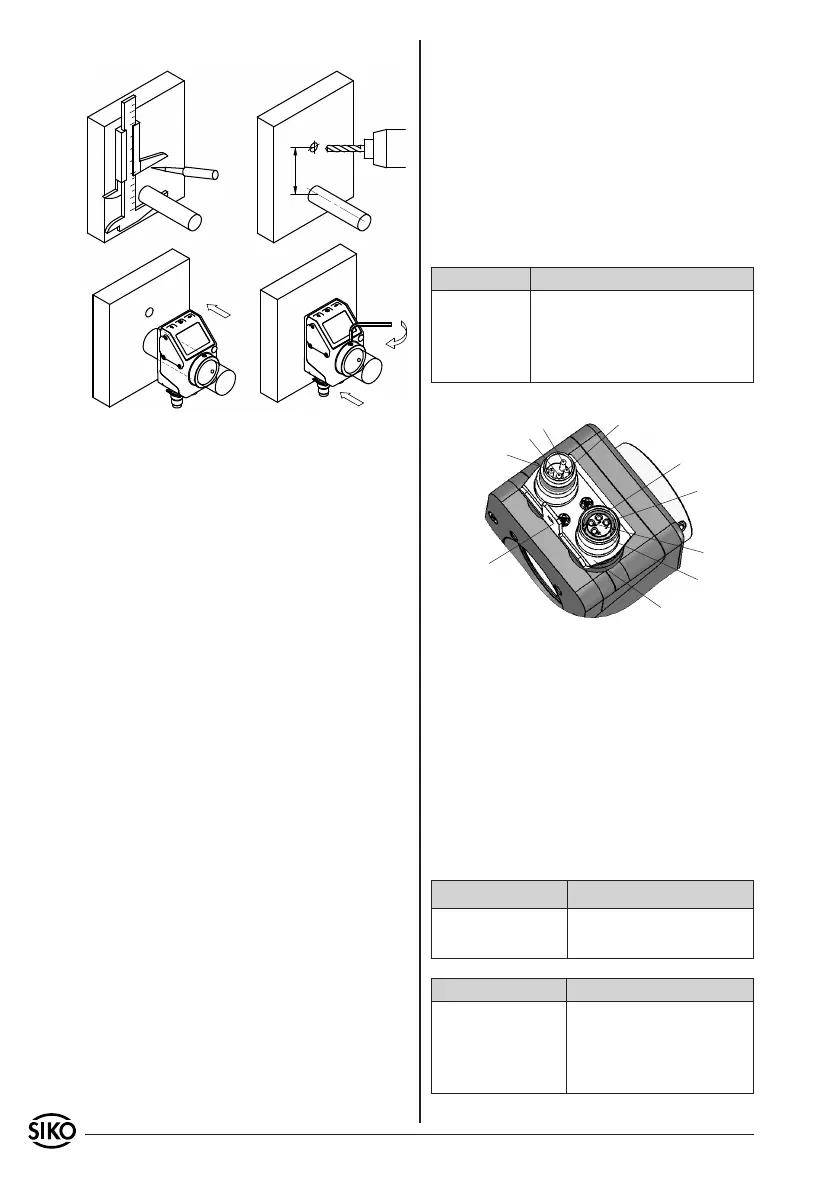
Fig. 1: Mounting instructions
Torque pin type A : pin-ø 6 h9
type B : bore-ø 10 +0.8
contact plate
1
2
3
4
PE connection
Bus-In
Bus-Out
1
2
3
4
Fig. 2: Pin connection
pression.
Power supply
24 VDC ±20%, with polarity protection
Power consumption depends on the device version:
RS485: ca. 16 mA
CAN: ca. 20 mA
additionally approx. 3 mA per LED
5.1 Connection
Pin Designation
1 DÜB/TxRx-/CANL
2 DÜA/TxRx+/CANH
3 +24VDC
4 GND
Live contacts must not be openly accessible. The-
refore, see to it that voltage is supplied via the
housing connector. Thus, the live contacts on the
output are protected by the bushing.
Apply the PE connector (6,3 mm flat connector)
between the coupler connectors jointly to protec-
tion conductor potential, fig. 3 (preferably short
strand 2,5 mm² ... 4 mm²)! For data transfer, the
cable lengths listed in the tables below are possible
depending on the baud rates.
RS485 baud rate Max. bus network length
115.2 kbit/s 200 m
19.6 kbit/s 1200 m
CAN baud rate Max. bus network length
125 kbit/s 320 m
250 kbit/s 160 m
500 kbit/s 80 m
1 Mbit/s 40 m
5. Electrical connection
• Switch power o before any plug is inserted or
removed!!
• Wiring must only be carried out with power o.
• Check all lines and connections before switching
on the equipment.
• Additionally fix the connection lines in order to
prevent mechanical strain from influencing the
mounted device.
Interference and distortion
All connections are protected against the eects
of interference. The location should be selected
to ensure that no capacitive or inductive inter-
ferences can aect the display or the connection
lines! Suitable wiring layout and choice of cable
can minimise the eects of interference (e.g. inter-
ference caused by SMPS, motors, cyclic controls and
contactors).
Necessary steps
• Only screened cable should be used. Wire cross
section is to be at least 0,14 mm
2
, max. 0,5 mm
2
.
• Wiring to screen and to ground (0 V) must be via
a good earth point having a large surface area for
minimum impedance.
• The unit should be positioned well away from
cables with interference; if necessary a protective
screen or metal housing must be provided. The
running of wiring parallel to the mains supply
should be avoided.
• Contactor coils must be linked with spark sup-
 Loading...