AP04 Datum 08.06.2011 Art.Nr. 84211 Änd. Stand 189/11 9
Fig. 3: Connection
PE-rail
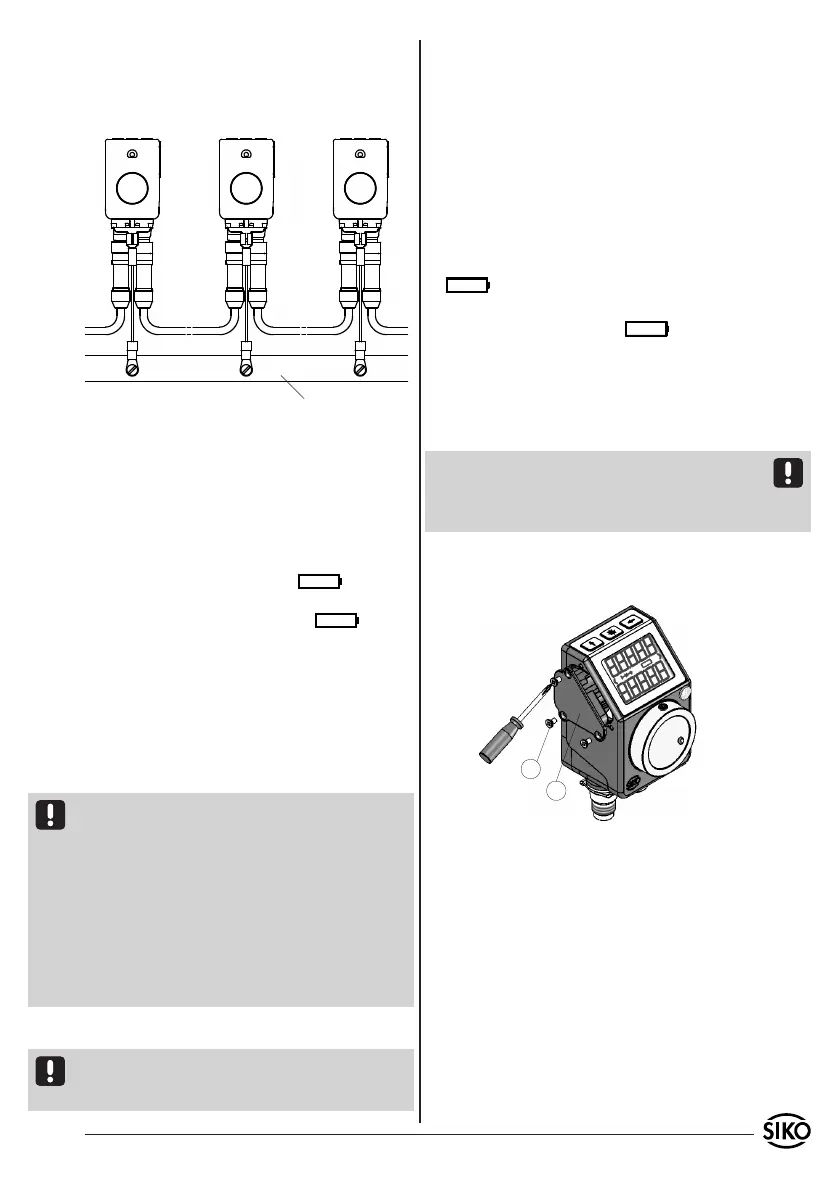
Fig. 4: Battery change
6. Battery back-up
The battery makes possible the detection of cur-
rentless displacement. Depending on the duration
of battery operation and the frequency of current-
less displacement, the battery life is approx. 5 to
8 years. Battery voltage is checked at intervals of
approx. 5 min. If battery voltage drops below a spe-
cified value, the battery symbol will blink
on the display. The battery is nearly empty. If the
battery voltage continues to drop, will be
displayed permanently. The battery should be re-
placed as soon as the battery symbol appears on
the display. The battery can be replaced by the SIKO
distribution partners or at the SIKO main factory.
If you prefer to replace the battery yourself, you
should observe the following points.
Safety information
Attention-Battery!
In order to avoid loss of calibration data, we recom-
mend to replace the battery while supply voltage is
being applied.
Caution! Do not insert pointed or metallic objects
into the housing after the battery compartment has
been removed!
Do not get your hands into the housing!
Inflammable, explosion and burning hazard. Can-
not be recharged and must not be punctured, bur-
ned or exposed to temperatures above 100 °C.
Battery change
Only exchange battery when operating voltage is
applied. By doing this, you can avoid sensor cali-
bration and reference travel.
The battery compartment is on the left side of the
housing (connections below). New, ready to be
used battery unit can be ordered from SIKO under
article no. 84208. For replacing the battery, per-
form the following steps:
• lay out ready the replacement battery.
• unscrew the three fastening screws (1) and remove
the battery compartment (2).
• insert new battery unit. Take care that it is easily
joinable (O ring must lie on the battery housing
during mounting).
• will disappear after completion of the next
measuring interval.
• In case of wrong contacting, will continue
to be displayed.
• Alternately, the device can be separated from
operation voltage for test purposes. Battery display
will be updated after the supply voltage has been
applied again.
Caution! The calibration of the sensor unit can get
lost if supply voltage is absent. In this case, cali-
bration travel will be required (see configuration
parameter "code 00100").
• Tighten fastening screws
• Discharged batteries should be disposed of safely.
7. Commissioning
The AP04 is switched on by applying supply voltage.
First, all display segments are shown in a self-test
and the green LED is lighted; then, the device name
and version number will be displayed for approx. 2
s and the red LED is lighted. During this time, the
required configuration data is loaded from the non-
volatile memory in the background.
RS485:
The AP04 is in the normal operational mode and
communicates with the preset SIKONETZ protocol
under the set address.
For the function on the bus, a terminator (120 Ohm)
is required, available from SIKO under art. code
BAS-0005. The terminator must be inserted on the
last bus subscriber between DÜA/TxRx+/CANH and
DÜB/TxRx-/CANL.
 Loading...