Do you have a question about the Siko AP10S and is the answer not in the manual?
Describes technical data, dimensions, pin assignments, and accessories for the product.
Explains notation for decimal, binary, and hexadecimal values used in the manual.
Details the initialization process after power-on and initial parameter loading.
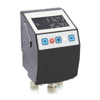
Overview of the two-line display and three control keys for parameterization and control.
Describes the two-row LC display, actual/set point display, and direction indicators.
Differentiates between Absolute Position, Differential Value, Modulo, and Alpha-numeric display modes.
Describes configuring parameters like node address, baud rate, etc., using the device's keyboard.
Lists key adjustable parameters such as Node-ID, Baud rate, Protocol, and Bus-Timeout.
States that full parameterization is possible via the RS485-SIKONETZ5 interface.
Discusses warnings like low battery voltage that do not affect position acquisition.
Covers error signaling via display/interface and provides corrective actions for common faults.
Details the process of alignment travel required for new/different sensors for optimal accuracy.
Details the two steps for calibration: writing calibration value and executing reset.
Describes the RS485 interface characteristics, including baud rates and data format.
Explains the master-slave communication protocol and data transfer optimization.
Details the structure of command and reply telegrams in Big-Endian format.
Explains setting the device address in the range 0-127 and the need for unique addresses.
Lists SIKONETZ5 specific error codes with descriptions for various communication faults.
Describes bus timeout monitoring activated by setting a timeout value.
Explains the programming interlock controlled by parameter OEh to prevent unintentional parameterization.
Setting the SIKONETZ5 node address, active after device restart.
Setting the SIKONETZ5 baud rate, active after device restart.
Indication of bus timeout in x100 ms, see chapter 6.7.1.
Duration of key actuation to start configuration.
Sets calibration value when calibrating the encoder position.
Sets the operating mode: Absolute position, Difference, Modulo, or Alpha-numeric.
Sets the sensor type, MS500H or GS04.
Provides identification details of the device, e.g., AP10S.
Executes the calibration process for the device.
Enables control via ASCII commands, not bus-compatible.
Lists error messages returned for wrong input.
Lists commands for device control via the service protocol.
| Brand | Siko |
|---|---|
| Model | AP10S |
| Category | Touch Panel |
| Language | English |