General Informaton
AP10S
Date: 04.09.2017 Art. No. 87826 Mod. status 269/17 Page 5 of 48
1 General Informaton
1.1 Dokumentation
The following documents describe this product:
The data sheet describes the technical data, the dimensions, the pin assignments, the
accessories and the order key.
The installation instructions describe the mechanical and electrical installation including
all safety-relevant requirements and the associated technical specification.
The user manual for commissioning and integrating the position indicator into a fieldbus
syste
These documents can also be downloaded at http://www.siko-global.com/p/ap10s.
Additional information and support for this device can also be found there.
1.2 Definitions
If not explicitly indicated otherwise, decimal values are given as figures without addition (e.
g. 1234), binary values are labeled with b (e. g. 1011b), hexadecimal values are identified by
h (e. g. 280h) after the figures.
2 Intended use
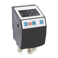
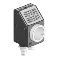
The device is an absolute position indicator with a plug-in connection for MS500H magnetic
sensor for direct linear distance measurement (combined with MB500 magnetic tape) or a
supported GS04 magnetic sensor for direct shaft mounting. Actual and target values are
indicated via the backlit two-row LC display. A direction indicator (arrow) is blended in if the
actual value deviates from the target value including the adjustable target window. The
direction of the arrow indicates the direction of shaft movement necessary to reach the
target. Additionally, various visualization tasks can be realized by means of two bi-color LEDs.
The device parameters can be adjusted by means of 3 keys. You can change the set point,
output the position value and adjust all device parameters via the integrated bus interface.
Scanning is magnetically-incremental. In the currentless state, scanning and saving of
changes of the position value are battery-supported.
The state of charge of the replaceable battery is monitored and signified.
If no sensor is connected or the MS500H sensor lifted off the tape, an error will be detected
and the position value displayed red with a flashing "Error" message. This condition survives a
power failure. The error must be remedied by way of calibration after checking the sensor
connection or sensor position, respectively.
Display and interface are active with external power supply only.