EasyManuals Logo

Siko AP05 Installation Instructions

Siko AP05
To Next Page IconTo Next Page
To Previous Page IconTo Previous Page
Page #25 background imageLoading...
Page #25 background image
AP05
Installation English
AP05 · Date 25.09.2018 · Art. No. 88847 · Mod. status 316/18
25
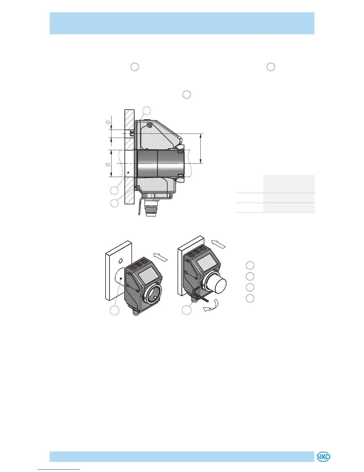
Mounting (Fig. 1, Fig. 2, Fig. 3):
1. Push the position indicator inclusive sealing plate onto the customer
shaft
3
until reaching the stop. Insert torque support
2
into the
existing bore (non-distorted mounting). A long hole for the torque sup-
port is recommended.
2. Tighten grub screws M3
4
with ≤0.2Nm.
D
1
2
3
d
L1
Fig. 1: Mounting dimensions
dim. ød ø6 (type A)
ø10
+0.8
(type B)
dim. L1 22
dim. øD ø20
(clearance fit)
Tab. 1: Mounting dimensions
1
Sealing plate
2
Torque support
3
Customer shaft
4
Grub screw
3
Fig. 2: Mounting
4
Fig. 3: Fastening torque
for screws

Other manuals for Siko AP05

Questions and Answers:

Question and Answer IconNeed help?

Do you have a question about the Siko AP05 and is the answer not in the manual?

Siko AP05 Specifications

General IconGeneral
BrandSiko
ModelAP05
CategoryMeasuring Instruments
LanguageEnglish

Related product manuals